CT metering explained: what technicians and engineers need to know
CT metering uses a current transformer meter paired with external current transformers to measure large currents indirectly — the CT reduces the primary current to a manageable secondary signal (typically 1 A or 5 A), and the meter multiplies that reading back by the CT ratio to display actual current and energy. A 200:5 CT, for example, produces a multiplier of 40 (200 ÷ 5), so a meter reading of 1,000 kWh becomes 40,000 kWh at the billing point. Direct metering is practical up to moderate currents per phase; above that, CT metering is the standard approach.
Three authoritative references underpin the practice:
- AS 61869-2:2021 (Standards Australia) — the primary standard for metering CT specification, accuracy class definitions and type-testing requirements
- SATEC Australia — detailed technical guidance on ratio, class and burden for revenue-grade installations
- Energex Metering Manual — a distributor-level reference for installation, labelling, test certificates and access requirements
Key takeaways
CT metering is the standard approach for any load above roughly 80–100 A per phase, and getting the ratio, accuracy class and secondary burden right at the design stage prevents the billing errors and safety hazards that dominate field complaints.
| Point | Details |
|---|---|
| CT multiplier rule | Divide primary by secondary (e.g. 200:5 = ×40); combined CT+PT multipliers multiply together. |
| Accuracy class for billing | Use Class 0.2S for revenue metering; Class 0.5S is acceptable for internal sub-metering. |
| Burden is the weak link | Calculate total secondary VA before specifying conductor size; long thin runs routinely exceed CT ratings. |
| Open secondary is a safety hazard | Always short CT secondaries at the test block before disconnecting; never leave a secondary open on a live primary. |
| Document everything | Record CT ratios, multipliers, test results and panel labels; hand over to the retailer or distributor before billing goes live. |
| Level 2 escalation | Hdlevel2electriciansydney handles revenue metering, NMI handover, distributor coordination and open-secondary make-safe work across Sydney. |
Table of Contents
- How CT metering works
- Worked ratio examples and verification checks
- What accuracy class and burden actually mean
- CT types and how to choose the right one
- What a CT metering installation includes and how to wire it correctly
- How to size CTs and design the secondary loop
- Common faults, diagnostics and safe testing
- Where CT metering is used in practice
- Standards, distributor requirements and documentation
- Pre-visit and commissioning checklist — and when to call a Level 2 electrician
- What the field actually teaches you about CT metering
- CT metering services from Hdlevel2electriciansydney
- Sources
How CT metering works
The measurement chain is straightforward once you see it as a system rather than a single device.
- Primary conductor — the live cable carrying the full load current passes through the CT’s window or around its bar-type core. No direct electrical connection is made to the primary circuit.
- CT core and secondary winding — the alternating magnetic flux induced by the primary current drives a proportional secondary current. A 200:5 CT produces 5 A secondary when 200 A flows in the primary, maintaining that ratio across its rated range.
- Secondary wiring — the secondary current travels through the CT secondary loop to the meter input terminals, passing through a test block or shorting block along the way.
- Meter input and scaling — the meter reads the secondary current (and voltage, if voltage transformers are used) and applies the programmed multiplier to calculate actual power and energy.
- Display and data output — the meter reports scaled values in real units (kW, kWh, A, V). Modern digital CT meters also report power quality metrics including power factor, harmonic distortion and demand, which makes them useful well beyond simple billing.
CT-only multiplier: a 500:5 CT gives a multiplier of 100. A meter reading of 500 kWh represents 50,000 kWh actual consumption.
Combined CT and PT multiplier: where voltage transformers are also used (common in high-voltage metering), the multipliers stack. A 200:5 CT (multiplier 40) combined with a 2.4:1 PT (multiplier 2.4) gives an overall billing multiplier of 96 (40 × 2.4). Every kWh the meter displays equals 96 kWh of actual energy.
Secondary output choice matters for meter compatibility. A 5 A secondary is the traditional standard and suits shorter secondary runs with heavier conductors. A 1 A secondary reduces the current in the secondary loop, which lowers the VA burden contribution from wiring resistance — a genuine advantage on longer cable runs.
Worked ratio examples and verification checks
Ratio arithmetic is the first thing to verify on any CT-metered installation. Getting it wrong means every billing figure is off by a fixed factor, often for months before anyone notices.
Ratio examples
| CT ratio | PT ratio | CT multiplier | PT multiplier | Combined multiplier | Typical use |
|---|---|---|---|---|---|
| 200:5 | None | 40 | 1 | 40 | LV commercial revenue metering |
| 500:5 | None | 100 | 1 | 100 | Large LV industrial load |
| 200:5 | 2.4:1 | 40 | 2.4 | 96 | HV transformer-rated metering |
| — | None | 200 | 1 | 200 | High-current industrial feeder |
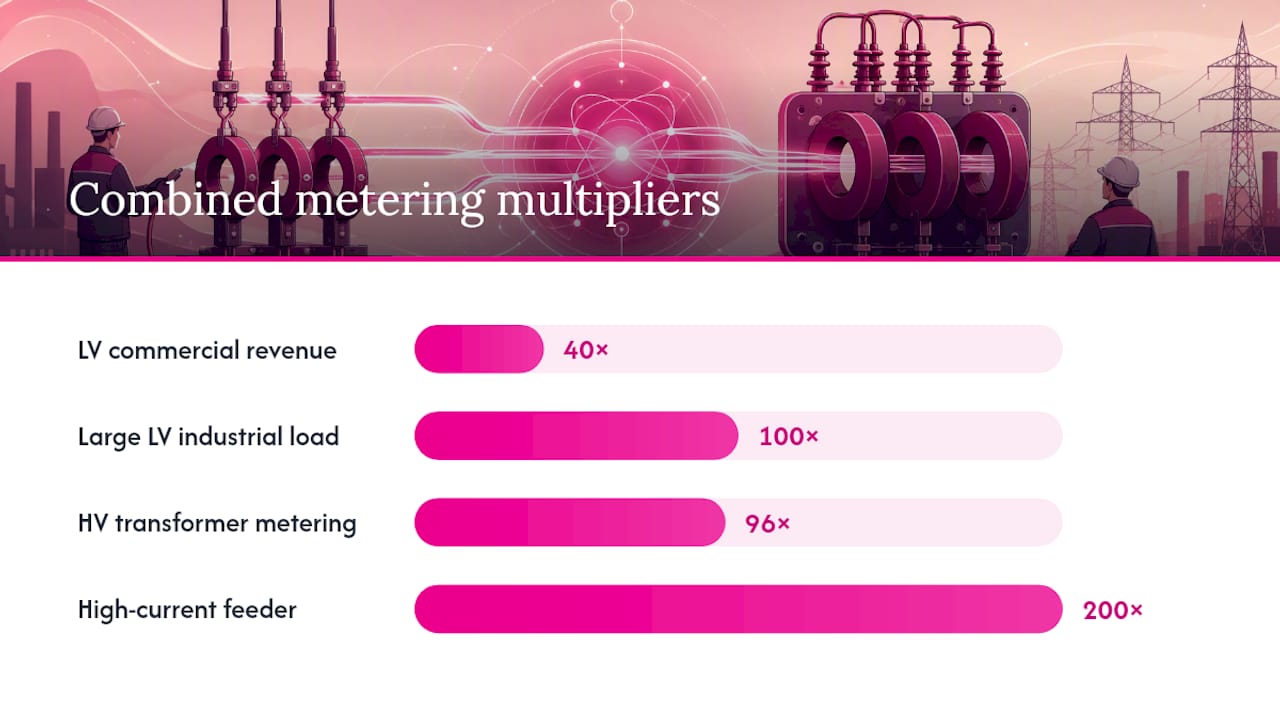
The multiplier is always primary ÷ secondary for each transformer. For combined systems, multiply the CT and PT multipliers together.
Three on-site verification checks
- Check the CT nameplate — confirm the ratio stamped on the CT body matches the single-line drawing and the ratio programmed in the meter. A 500:5 CT programmed as 200:5 will under-read by 60%.
- Confirm the meter configuration — access the meter’s ratio settings and compare them against the commissioning documentation. Many meters store this in a protected register; bring the meter’s programming tool or access code.
- Compare a spot measurement — use a calibrated clamp meter on the primary conductor and compare the reading against the meter’s displayed current scaled by the multiplier. A discrepancy greater than the CT’s stated accuracy class tolerance warrants investigation.
Pro Tip: Take a photo of the CT nameplate and the meter’s ratio configuration screen at commissioning. That two-minute step saves hours of dispute resolution if billing queries arise later.
What accuracy class and burden actually mean
Accuracy class defines the maximum permissible ratio error at rated conditions — a Class 0.2 CT will not deviate from its stated ratio by more than 0.2% at rated current and rated burden. Lower class numbers mean tighter tolerance. Standard classes run from 0.2, 0.2S, 0.5, 0.5S, 1.0, 2.0 through to 3.0.
The “S” suffix matters for billing. A Class 0.2S CT maintains its 0.2% accuracy down to 1% of rated primary current, whereas a standard Class 0.2 only guarantees that tolerance from 5% upward. For sites with variable or low-load periods — retail tenancies, off-peak tariff installations — the S variant prevents systematic under-reading during light-load hours.
Choosing the right class:
- Revenue billing (NMI-level): Class 0.2 or 0.2S — required by most distributor metering manuals for revenue-grade accuracy
- Sub-metering and tenant billing: Class 0.5 or 0.5S — acceptable where the billing is internal rather than network-facing
- Load monitoring and power quality: Class 1.0 — adequate for trend analysis and demand profiling
Burden and why wiring degrades accuracy
Burden is the total impedance the CT secondary sees, expressed in VA. It includes the meter’s input impedance, the secondary wiring resistance, and the resistance of connectors and test blocks. Long secondary runs with thin conductors can push total burden above the CT’s VA rating, causing the CT to operate outside its accuracy specification and typically produce an under-reading.
A CT rated at 5 VA burden with a meter consuming 1 VA still has 4 VA available for wiring. A 10-metre run of 2.5 mm² cable adds roughly 0.14 Ω per conductor (two conductors = 0.28 Ω), which at 5 A secondary equates to 7 VA — already over budget. Stepping up to 4 mm² or switching to a 1 A secondary output cuts that contribution substantially.
Pro Tip: *Always calculate secondary burden before specifying conductor size. Add the meter’s stated input VA, the test block resistance, and the cable VA at rated secondary current.
CT types and how to choose the right one
The physical form of a CT determines whether it can be installed at all in a given situation, and the electrical specification determines whether it will measure accurately.
Common CT types:
- Window (toroidal) CT — the primary conductor passes through a central aperture. Solid-core construction; must be installed during initial wiring or when the primary conductor can be de-energised and disconnected. Best accuracy and lowest cost for new installations.
- Split-core CT — the core opens to clamp around an existing conductor without disconnection. The preferred choice for retrofits and sub-metering upgrades where outages are not practical. Slightly higher cost and marginally lower accuracy than solid-core equivalents, but the trade-off is almost always worthwhile.
- Bar-type CT — the primary conductor is a solid copper bar that forms part of the CT assembly. Used in switchboard busbars and high-current applications; very stable and accurate.
- Metering CTs vs protection CTs — protection CTs are designed to avoid saturation during fault currents, which means they have a larger core and different burden characteristics. Using a protection CT for revenue metering is a common mistake; the core design optimises for fault-current linearity, not accuracy across the normal load range. Always specify a metering-class CT for billing applications.
Selection checklist:
- Ratio: sized so normal operating current sits at 60–80% of rated primary (see sizing section below)
- Accuracy class: 0.2S for revenue billing, 0.5S for sub-metering
- Burden rating: confirmed against calculated secondary loop VA
- Physical aperture: conductor diameter or busbar dimensions must fit the CT window
- Voltage rating: insulation must suit the system voltage
- Shorting arrangement: confirm the CT has integral shorting links or that the test block provides this function
- Environmental rating: IP rating appropriate for the enclosure and ambient conditions
Standard primary ratios run from 50:5 up to 4000:5, with split-core models widely available across that range for retrofit work.
What a CT metering installation includes and how to wire it correctly
A CT metering installation is a system. The meter, CTs, test block, secondary wiring, and any voltage transformers all interact — a weakness in any one component degrades the whole.
Typical components for a revenue metering panel:
- Revenue-grade CT meter (Class 0.2 or 0.2S input rating)
- Metering-class CTs, one per phase (and neutral if required)
- Test block or shorting block — allows secondary isolation and testing without opening the CT circuit
- Secondary wiring: minimum 2.5 mm² copper, 4 mm² for runs over 5 metres at 5 A secondary
- Voltage transformer(s) if the system is transformer-rated
- Meter sealing provisions (lock, seal wire, or tamper-evident cover)
- Labelling: CT ratio, polarity marks, and meter multiplier on the panel door
Wiring do’s and don’ts:
- Do run secondary cables in a dedicated conduit or cable tray, separate from power cables, to avoid induced interference.
- Do maintain polarity — the CT’s P1/P2 primary terminals and S1/S2 secondary terminals must be connected consistently with the meter’s phase convention. Reversed polarity causes the meter to read negative power on that phase.
- Do earth one point of the CT secondary circuit (typically the S2 terminal or the test block earth terminal) per the meter manufacturer’s instructions.
- Don’t run secondary cables in long loops or coils — excess length adds resistance and inductance.
- Don’t use undersized conductors to save cost on a long run. The VA penalty is real and permanent.
- Don’t leave a CT secondary open while the primary conductor is energised.
Pro Tip: Short the CT secondary at the test block before disconnecting any secondary wiring. An open CT secondary with a live primary can develop lethal voltages — this is one of the most serious hazards in metering work and is non-negotiable.
How to size CTs and design the secondary loop
Size CTs so normal operating current sits at 60–80% of the rated primary. A 400 A feeder with a typical demand of 280 A sits at 70% of a 400:5 CT — well within the linear accuracy range. Push that same load through an 800:5 CT and normal demand drops to 35% of rated primary, where accuracy degrades noticeably and billing errors accumulate.
Undersizing carries the opposite risk. A 200:5 CT on a 400 A feeder will saturate during normal operation, producing severe distortion and under-reading. During fault conditions, saturation is near-certain and the secondary output becomes unreliable.
Secondary burden calculation example:
A 200:5 CT rated at 5 VA feeds a meter 8 metres away. Secondary conductor is 2.5 mm² copper (resistance approximately 0.0073 Ω/m).
- Cable resistance (two conductors, 8 m each): 2 × 8 × 0.0073 = 0.117 Ω
- VA from cable at 5 A: 5² × 0.117 = 2.9 VA
- Meter input: 1 VA (from datasheet)
- Test block: 0.2 VA (estimated)
- Total burden: 4.1 VA — within the 5 VA rating, but only just
Extending that run to 12 metres pushes total burden to approximately 5.5 VA, exceeding the CT’s rating. The fix: step up to 4 mm² conductor (resistance approximately 0.0046 Ω/m), which brings the cable contribution down to 1.8 VA and total burden to 3.0 VA.
Design checklist for drawings and handover:
- CT ratio, accuracy class and VA burden rating noted on the single-line diagram
- Secondary conductor size and run length documented
- Calculated total burden recorded and confirmed within CT rating
- Meter multiplier(s) recorded on the panel schedule and in the commissioning report
- Test block location and shorting arrangement shown on the drawing
- Earthing point identified and labelled
Common faults, diagnostics and safe testing
The most frequent CT metering faults are wrong ratio programming, excessive secondary burden from long or undersized wiring, reversed polarity on one phase, and open secondary hazards discovered during maintenance. Most of these are preventable at commissioning; the ones that slip through tend to surface during billing audits or power quality investigations.
Diagnostic sequence:
- Visual and label check — confirm CT nameplate ratio against the single-line drawing and the meter’s programmed ratio. Check polarity markings on the CT and trace secondary wiring to the meter terminals.
- Secondary continuity — with the primary de-energised and the CT secondary shorted at the test block, measure continuity through each secondary loop. An open circuit indicates a broken conductor or loose terminal.
- Polarity check — with the primary energised, use a phase-angle meter or a meter with phasor display to confirm each phase’s current phasor is in the expected relationship to its voltage. A reversed CT on one phase shows as a 180° phase shift on that channel.
- Burden measurement — measure secondary loop resistance with a calibrated milliohm meter and calculate VA at rated secondary current. Compare against the CT’s rated burden.
- Comparison measurement — clamp a calibrated reference meter on the primary conductor and compare the scaled reading against the revenue meter’s display. Acceptable tolerance depends on the CT’s accuracy class.
Safety checklist for on-site testing:
- Isolate the primary circuit where possible before working on secondary wiring
- Short CT secondaries at the test block before disconnecting any secondary terminal
- Use test equipment rated for the system voltage and secondary current
- Wear appropriate PPE: insulated gloves, safety glasses, arc-rated clothing where required
- Never work alone on energised metering equipment
Acceptable on-site tolerance for a Class 0.2 installation is ±0.2% at rated current.
Where CT metering is used in practice
CT metering suits any situation where direct connection to the primary circuit is impractical, unsafe, or where the load current exceeds the meter’s direct-connect rating.
Typical applications:
- Commercial revenue metering — the most common use case. A retail or office building drawing 200–2,000 A at the main switchboard uses CT metering for the network connection point (NMI). The distributor specifies the CT class and ratio; the installer provides the test certificate.
- Multi-tenant sub-metering — individual tenancy meters in a strata or commercial building use CT metering to allocate energy costs. Class 0.5S CTs are typical; the multiplier is recorded in the building management system.
- Retrofit sub-metering — split-core CTs allow sub-meters to be added to existing switchboards without disconnecting live conductors. A smart meter upgrade combined with split-core CTs can deliver tenant-level billing data within a single day’s work.
- Power quality monitoring — modern CT meters report harmonics, power factor and demand alongside energy. Facility managers use this data to identify failing motors, capacitor bank issues and tariff optimisation opportunities. Power logging studies using temporary CT-based loggers are a standard first step before any major electrical upgrade.
- Protection schemes — protection CTs feed relay inputs rather than meters. The design priority shifts from accuracy across the load range to reliable operation during fault conditions; these CTs are not interchangeable with metering CTs.
Standards, distributor requirements and documentation
AS 61869-2:2021 is the primary Australian standard for metering current transformers, covering accuracy class definitions, type-testing requirements and the test points that revenue CTs must satisfy. Any CT specified for network-facing revenue metering should carry type-test certification to this standard.
Distributor metering manuals add site-specific requirements on top of the standard. The Energex Metering Manual is a representative example: it requires NATA-accredited accuracy test reports, minimum test points at 5%, 20%, 100% and maximum rated primary current, specific labelling on CT bodies and the metering panel, defined clearance and access arrangements, and sealing of the meter and test block after commissioning. Other distributors publish equivalent documents; always check the relevant distributor’s current metering manual before specifying equipment.
Documentation required for revenue CT installations:
- NATA-accredited type-test certificate for each CT model, confirming accuracy class and burden rating
- Commissioning report recording CT ratios, meter serial number, programmed multiplier and test results
- Single-line diagram showing CT locations, secondary wiring routing, test block position and earthing point
- Panel label showing CT ratio, meter multiplier and date of commissioning
- Handover record to the retailer or distributor confirming the billing multiplier
| Document | Purpose | Who holds it |
|---|---|---|
| NATA type-test certificate | Proves CT meets accuracy class | Installer, distributor |
| Commissioning report | Records ratios, multipliers, test results | Installer, site owner |
| Single-line diagram | Shows system layout and wiring | Site owner, distributor |
| Panel label | Quick-reference multiplier for meter readers | Panel door |
| Retailer/distributor handover | Confirms billing multiplier for tariff setup | Retailer, distributor |
Commercial electrical compliance documentation should include all of the above; missing records are the most common reason distributor acceptance is delayed.
Pre-visit and commissioning checklist — and when to call a Level 2 electrician
A structured approach at each stage prevents the errors that cause billing disputes and safety incidents.
Pre-visit checks:
- Obtain and review the single-line drawing — confirm CT locations, ratios and secondary routing are shown.
- Check the distributor’s current metering manual for any site-specific requirements (CT class, test certificate format, access clearances).
- Confirm existing CT labels match the drawing; photograph any discrepancies before touching anything.
- Verify the meter’s programmed multiplier against commissioning records.
On-site commissioning checklist:
- Confirm CT polarity markings and trace secondary wiring to the meter terminals before energising.
- Verify shorting links are in place at the test block before any secondary wiring is disturbed.
- Measure secondary loop continuity and resistance; calculate total burden and confirm it is within the CT’s VA rating.
- Energise and check phasor display for correct phase relationships on all three phases.
- Perform a comparison measurement with a calibrated reference; record results in the commissioning report.
- Apply seals or lock provisions as required by the distributor; photograph the completed installation.
Escalation triggers — call a Level 2 electrician when:
- An open CT secondary is found or suspected while the primary is energised
- CT saturation is indicated (secondary current non-linear or distorted under normal load)
- Revenue-grade accuracy cannot be verified within the CT’s stated class tolerance
- The installation requires distributor access, sealing, or NMI handover
- The CT or meter requires replacement under a distributor’s metering agreement
- Any work involves the network connection point or the service fuse
Pro Tip: Collect the CT nameplate photo, meter serial number, programmed multiplier screenshot, and a copy of the single-line diagram before leaving site. Hand these to the retailer or distributor as a single PDF — it removes ambiguity from the billing setup and protects you if a query arises months later.
What the field actually teaches you about CT metering
Most CT metering problems are not hardware failures. The CT is usually fine. The meter is usually fine. The issue is almost always in the gap between specification and installation: a ratio programmed from memory rather than the nameplate, a secondary run that grew by three metres during the fit-out and was never recalculated, or a CT that was the right size for the connected load but not for the actual demand profile.
The second pattern worth noting is the documentation gap. A commissioning report that records the multiplier but not the secondary conductor size or the burden calculation leaves the next technician with no baseline. When a billing query surfaces eighteen months later, the investigation starts from scratch. The sites that handle these queries quickly are the ones where someone took the time to photograph the CT nameplate, the meter configuration screen, and the test block before closing the panel.
Hdlevel2electriciansydney’s Level 2 team sees both patterns regularly. The resolution is usually straightforward once the correct ratio is confirmed and the secondary burden is measured — but the time cost of an unplanned site visit, a distributor notification and a billing correction is significant. Getting it right at commissioning is always the faster path.
CT metering services from Hdlevel2electriciansydney
When a CT metering installation needs to be done to distributor standard — with the test certificates, NMI handover and sealing that revenue metering requires — that is Level 2 work, and it needs a certified contractor familiar with processing fees.

Hdlevel2electriciansydney provides the full scope: CT meter installation and upgrades, meter relocation where panel changes are needed, secondary wiring remediation, on-site verification against distributor requirements, and NMI handover coordination with the retailer. The team also handles open-secondary make-safe callouts and electrical safety inspections for existing CT metering panels that haven’t been verified in years. Free site inspections are available for Level 2 metering work — bring your single-line drawing, existing CT labels and any distributor correspondence, and the team will assess what’s needed before any work begins. To book a site visit or request a quote, contact the Level 2 electrician Sydney team directly.
Sources
- CT Meter Accuracy Explained: What Ratio, Class and Burden Really Mean - SATEC (Australia) Pty Ltd
- Introduction to CT measurements - Weschler
- Queensland Electricity Metering Manual (Energex) - selectra / Energex PDF
- What is a Current Transformer Meter? - Eastron / EastroN Group
Recommended
Powering Your Needs with Expertise
If you’re looking for a reliable, experienced, and prompt electrician, look no further than High Demand Electrical. We cater to all your electrical needs, from routine maintenance to emergency repairs and complete system installations. Our skilled team is committed to providing professional service that ensures your electrical systems run smoothly. Whether it's a small task or a large project, give us a call today. Let us meet all your electrical demands with the quality and reliability you deserve.