Cut kVA Waste: Power Factor Correction Basics for Engineers & Business
Power factor correction supplies reactive power locally so more of the electricity delivered actually does useful work, moving power factor closer to 1. It’s usually required when large inductive or highly distorted loads drag power factor down, or when a utility applies demand penalties tied to reactive consumption.
Power factor correction basics: real, reactive and apparent power explained
Every electrical load draws two kinds of power. Real power, measured in kilowatts (kW), does the actual work: turning a motor shaft, lighting a room, running a compressor. Reactive power, measured in kilovolt-amperes reactive (kVAR), doesn’t do useful work at all. It builds and collapses the magnetic fields inside motors, transformers and ballasts, and it sloshes back and forth between the source and the load without ever being consumed.
Apparent power, measured in kilovolt-amperes (kVA), is what the supply network actually has to deliver to satisfy both. The three sit together in what engineers call the power triangle: kW along the base, kVAR up the side, and kVA as the hypotenuse joining them. Power factor is simply the ratio between the two: PF = P/S = cosφ, where φ is the phase angle between voltage and current.
A power factor of 1.0 means every amp delivered is doing real work. A power factor of 0.7 means the network is carrying 43% more current than the real power alone would require, according to the IET’s power factor correction guidance. That extra current still has to be generated, transformed, distributed and paid for.
One nuance worth flagging early: cosφ describes displacement power factor, the phase shift between voltage and current at the fundamental frequency. Where harmonics are present, a separate distortion factor also drags down the true or “total” power factor. We’ll come back to why that split matters when picking a correction method.

What causes poor power factor on site
Lagging power factor almost always traces back to one of two sources: inductive equipment or non-linear electronics.
Inductive loads are the classic culprit. They draw current that lags voltage because of the magnetic fields they rely on to operate:
- Induction motors driving pumps, fans, conveyors and compressors, especially when running lightly loaded.
- Transformers, which draw magnetising current even at low load.
- Refrigeration, coolrooms and HVAC plant.
- Older fluorescent and HID lighting with magnetic ballasts.
- Welding equipment and induction heating.
Non-linear loads behave differently. Switch-mode power supplies (SMPS) and variable frequency drives (VFDs) chop the incoming waveform into pulses rather than drawing a smooth sine wave, which injects harmonic currents back into the network. An SMPS without any correction circuitry commonly sits around a power factor of 0.55 to 0.75, even though the unit itself might be perfectly efficient at converting energy.
Sites that commonly show low power factor include buildings with many small, lightly loaded motors, older HVAC plant, and data centres or offices packed with switch-mode electronics. If your load profile matches any of that, poor power factor is worth investigating before it shows up as a penalty line on your energy bill.
Passive capacitor banks, switched APFC and active PFC compared
Correcting power factor means supplying reactive power locally, close to the load, so the wider network doesn’t have to carry it. There are three broad approaches, and the right one depends heavily on how steady or distorted your load is.
Fixed capacitor banks are the simplest option: a bank of capacitors permanently connected to supply a set amount of leading kVAR that offsets the lagging kVAR from inductive equipment. They’re cheap and low-maintenance, but they can’t adapt. If the inductive load drops off overnight, a fixed bank can overcorrect and push power factor leading, which causes its own voltage problems.
Switched or automatic power factor correction (APFC) panels solve that by breaking the capacitance into stages and switching them in and out under controller logic, tracking the load in real time to hold power factor within a preset band. This is the standard fit for facilities where load varies through the day, such as manufacturing sites or mixed-use commercial buildings, according to background on automatic PFC panel operation.
Active PFC, built from power electronics rather than switched capacitors, shapes the input current waveform to follow the supply voltage directly. It’s the approach embedded in most modern SMPS and increasingly in plant-level compensation using boost-topology converters. Where harmonic distortion is significant, active PFC is the safer bet because it can lift power factor above 0.99 while simultaneously reducing harmonic content, something passive banks cannot do on their own, according to TechTarget’s explainer on power factor correction.
At the larger end of the scale, synchronous condensers and static VAR compensators (SVC/STATCOM) provide dynamic reactive support for heavy industrial or grid-connected applications, though most commercial and light industrial sites will never need to go there.
The trade-offs in short:
How to calculate the kVAR you need to correct power factor
Sizing a capacitor bank comes down to one formula that every power quality engineer uses: Qc = P × (tanφ1 − tanφ2), where P is real power in kW, φ1 is the phase angle at your existing (uncorrected) power factor, and φ2 is the phase angle at your target power factor, as set out in ECMweb’s primer on power factor correction.
To get there, follow this sequence:
- Measure real power (kW) and the existing power factor at your site’s maximum demand.
- Choose a target power factor, usually 0.95 or whatever your network or tariff requires.
- Find tanφ1 and tanφ2 for the existing and target power factors.
- Multiply the kW by the difference between them to get the kVAR required.
- Round up to the nearest available capacitor step, and use switched or automatic correction if the load varies through the day.
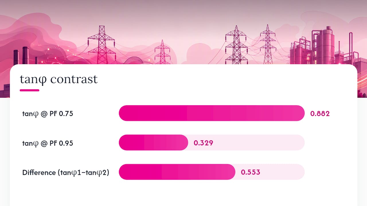
Worked example: A workshop draws 100 kW at an existing power factor of 0.75, and the goal is to reach 0.95.
- tanφ1 at 0.75 power factor = 0.882
- tanφ2 at 0.95 power factor = 0.329
- Qc = 100 × (0.882 − 0.329) = about 55 kVAR, so a 55 to 60 kVAR bank
That’s the capacitor rating needed to shift this load from 0.75 to 0.95 power factor. Utilities generally expect industrial and commercial customers to hold power factor somewhere in the 0.90 to 0.95 range, and a well-tuned installation using this method should land there comfortably, provided the bank is sized for worst-case, not average, conditions.
Pro Tip: Always size the calculation off your minimum recorded power factor, not the average. If you size for a typical day and the load drops during a quiet period, a fixed bank can overcompensate and push the system into a leading power factor, which brings its own voltage headaches.
If you’d rather skip the manual maths, High Demand Electrical’s free electrical calculators include a maximum demand tool that helps ballpark the load side of this equation before you commit to equipment.
Why correcting power factor pays off
Improving power factor cuts the current flowing through cables, transformers and switchgear for the same amount of real power delivered. Lower current means lower I²R losses throughout the distribution system, and it means better voltage regulation at the load, particularly on long feeders or heavily loaded transformers, an effect the IEEE’s technology overview attributes directly to local reactive supply.
Most network operators set a target band, commonly 0.90 to 0.95, and bill customers who fall short through demand or reactive power charges. For many commercial sites, the economic case for correction hinges less on straight energy savings and more on avoiding those kVA-based demand charges, which makes understanding your tariff structure just as important as understanding your load.
Correcting power factor also frees up capacity. A transformer or switchboard rated in kVA can carry more real load once reactive current is stripped out, sometimes avoiding an expensive upgrade altogether. Payback varies with tariff design and load profile, but sites carrying heavy reactive demand often see the equipment pay for itself within a couple of years. Folding this into a broader energy management approach makes the numbers even more compelling for businesses tracking operating costs closely.
Harmonics, resonance and when passive correction turns risky
Capacitors and harmonics don’t always mix well. Every capacitor bank forms a resonant circuit with the system’s inductance, and if that resonant frequency lines up with a harmonic already present from VFDs, SMPS or other non-linear loads, the result is amplified voltage and current at that frequency. That can overheat capacitors, trip protective devices, or damage sensitive equipment elsewhere on the network.
The fix isn’t to avoid capacitors altogether. It’s to detune the bank, adding a small series reactor that shifts the resonant point below the lowest troublesome harmonic, or to fit tuned filters designed to absorb specific harmonic orders. Where distortion is severe, active filtering or active PFC sidesteps the resonance risk entirely because it doesn’t rely on a fixed capacitive reactance.
Pro Tip: If more than a third of your site’s load is VFDs, SMPS or LED drivers, assume you’ll need a detuned bank or active correction from the outset. Skipping straight to a plain fixed capacitor bank on a harmonic-heavy site is one of the most common (and expensive) mistakes we see.
Good protective design also includes correctly rated fusing, surge arrestors, and periodic power quality scans to catch drift before it becomes a fault, in line with the safe connection practices set out in the NSW Service and Installation Rules.
Measuring power factor and deciding if correction is worth it
You can’t size anything reliably without measurement first. A power quality analyser with logging capability is the right tool for this job. It captures kW, kVAR, power factor and total harmonic distortion (THD) over time, rather than the single-instant snapshot a basic clamp meter gives you.
What to log and check:
- kW, kVA, kVAR and power factor on each phase over at least a week of normal operation.
- Voltage and current total harmonic distortion (THD).
- When peak demand happens and which loads are running at the time.
- Transformer loading against its kVA rating.
- The condition and switching of any existing capacitor banks.
Correction is worth pursuing when you see recurring reactive demand charges on your bill, power factor sitting persistently below your utility’s target band, voltage sag under load, or a transformer running close to its kVA rating. Before signing off on any contractor’s proposal, ask how they calculated the kVAR requirement, whether they checked THD before specifying passive capacitors, and what protection (fusing, detuning) is built into the design. Rapid, unexplained swings in reactive demand or unusually high THD readings are red flags worth a proper fault-finding investigation before any capacitor gets installed.
How a Level 2 electrician handles power factor correction work
Power factor correction often touches supply-side infrastructure, which in New South Wales means work that falls under Level 2 electrician services accreditation. That covers connecting capacitor banks or APFC panels where they interact with the network supply, and any switchboard upgrade needed to accommodate the new equipment safely and to the standard required by NSW’s service and installation rules.
Free site inspections are often offered for this kind of Level 2 work, giving business and facilities managers a clear picture of scope before committing to equipment. A straightforward, steady industrial load with mild harmonic content might only need a simple APFC panel. A site with heavy VFD or SMPS use, voltage instability, or supply-side switchboard constraints warrants a specialist assessment first, ideally paired with an electrical safety inspection to confirm what’s actually driving the low power factor before equipment gets ordered.
The bottom line on fixing your power factor
Measure before you buy. Prefer APFC or active correction over a plain fixed bank whenever your load is variable or your harmonic profile is anything but clean. From there: arrange a logging audit, run the kVAR calculation against your worst-case power factor, and get a professional quote before equipment goes on order.
What the textbooks get wrong about power factor correction
Most introductory material treats power factor correction as a pure maths problem: measure PF, apply the formula, install capacitors, done. That framing misses the part that actually determines whether the project succeeds, which is the harmonic content of the load, not just its reactive component.
The gap between the textbook and the real building is this: a facility with clean, steady inductive loads and a facility stuffed with VFDs and switch-mode electronics can show the identical uncorrected power factor on paper, yet need completely different equipment. Treat them the same, and you either waste money on active PFC where a $2,000 capacitor bank would have done the job, or you install a plain fixed bank that resonates with existing harmonics and fails within eighteen months.
If there’s one priority for a reader working through this for the first time, it’s this: don’t calculate kVAR before you’ve logged THD. The sizing formula is the easy part. Knowing whether your load tolerates a passive solution is the part that actually separates a correction project that pays for itself from one that becomes next year’s fault call. Engineers who skip that step aren’t cutting corners on theory, they’re gambling on equipment they haven’t actually characterised.
Related Services

Powering Your Needs with Expertise
If you’re looking for a reliable, experienced, and prompt electrician, look no further than High Demand Electrical. We cater to all your electrical needs, from routine maintenance to emergency repairs and complete system installations. Our skilled team is committed to providing professional service that ensures your electrical systems run smoothly. Whether it's a small task or a large project, give us a call today. Let us meet all your electrical demands with the quality and reliability you deserve.