Main switch rating: what electricians need to know
A main switch rating covers two separate things: how much continuous current it can carry (amps) and how much fault current it can safely interrupt (kA, or AIC). Get either wrong and you have a switch that either trips nuisance-fast or welds itself shut during a fault. The rule of thumb is simple: amp rating must sit at or above your calculated maximum demand, breaking capacity must exceed the prospective fault current at that point, and if you’re switching motors, you need an AC-23A rated switch, not a basic isolator.
Table of Contents
- What is a main switch rating, technically speaking?
- What are typical nominal main switch ratings for different installations?
- How do you size a main switch correctly?
- Which pole configuration suits your supply type?
- Why does AC-23A matter for motor-heavy installations?
- What should a selection and installation checklist cover?
- What do real-world main switch checks actually look like on-site?
- Need help sizing or upgrading your main switch?
- A Level 2 contractor’s take on where main switch sizing goes wrong
- Sources
What is a main switch rating, technically speaking?
A main switch rating is not one number. It’s really three, and confusing them is where most sizing errors start.
The amp rating is the continuous thermal carrying capacity of the switch. It tells you how much current the switch can handle indefinitely without overheating. This is not the sum of the MCB ratings on the board behind it. A board with ten 20 A circuits does not need a 200 A main switch, because no house or business runs every circuit at full load simultaneously.
The breaking capacity, expressed in kA (kiloamps) or AIC (amps interrupting capacity), is the peak short-circuit current the switch can safely interrupt without the contacts welding or arcing dangerously. Every point on a network has a “prospective fault current”, the theoretical current that would flow if a dead short occurred right at that point. Closer to the transformer, that figure climbs, which is why commercial three-phase boards often need higher kA switches than a suburban house.
Then there’s utilisation category, defined by standards like IEC60204-1 and AS/NZS 4024.1204. AC-21 covers occasional switching of resistive loads. AC-22 covers mixed resistive and inductive loads. AC-23 and AC-23A cover motor circuits, where the switch must make and break locked-rotor current, a spike that can be six to eight times the motor’s running current.
What are typical nominal main switch ratings for different installations?
Most single-phase residential installations in built form use a main switch sized to typical household maximum demand once diversity is applied across cooking, hot water, lighting and general power, and this will align with what the local supply authority’s service fuse or meter can actually deliver.
Step up to small commercial premises or larger homes with heat pumps, EV chargers and pool equipment, and a higher main switch rating becomes common. Three-phase supplies for medium commercial sites often require larger ratings, and heavy industrial or large multi-tenant buildings may require switches rated for significantly more current.
None of these figures exist in isolation. The switch you can fit is often capped by the physical rating stamped on the switchboard itself, and by what the network operator’s service fuse or transformer capacity will allow. Practitioners on trade forums regularly flag jobs where the board’s own stamped maximum rating becomes the real ceiling, not the customer’s wish list. If a client wants more capacity than the existing board or service allows, the conversation moves quickly from “bigger main switch” to an electrical service upgrade.
How do you size a main switch correctly?
Sizing a main switch is a calculation, not a guess, and it’s not addition either.
1. Gather the load data. List every connected load: lighting, general power, hot water, air conditioning, motors, EV chargers. Note which loads are continuous and which are intermittent, and record the supply fuse or transformer rating. Ask the network operator directly for the prospective fault current at the point of connection. Guessing this figure is the single most common shortcut that comes back to bite installers later.
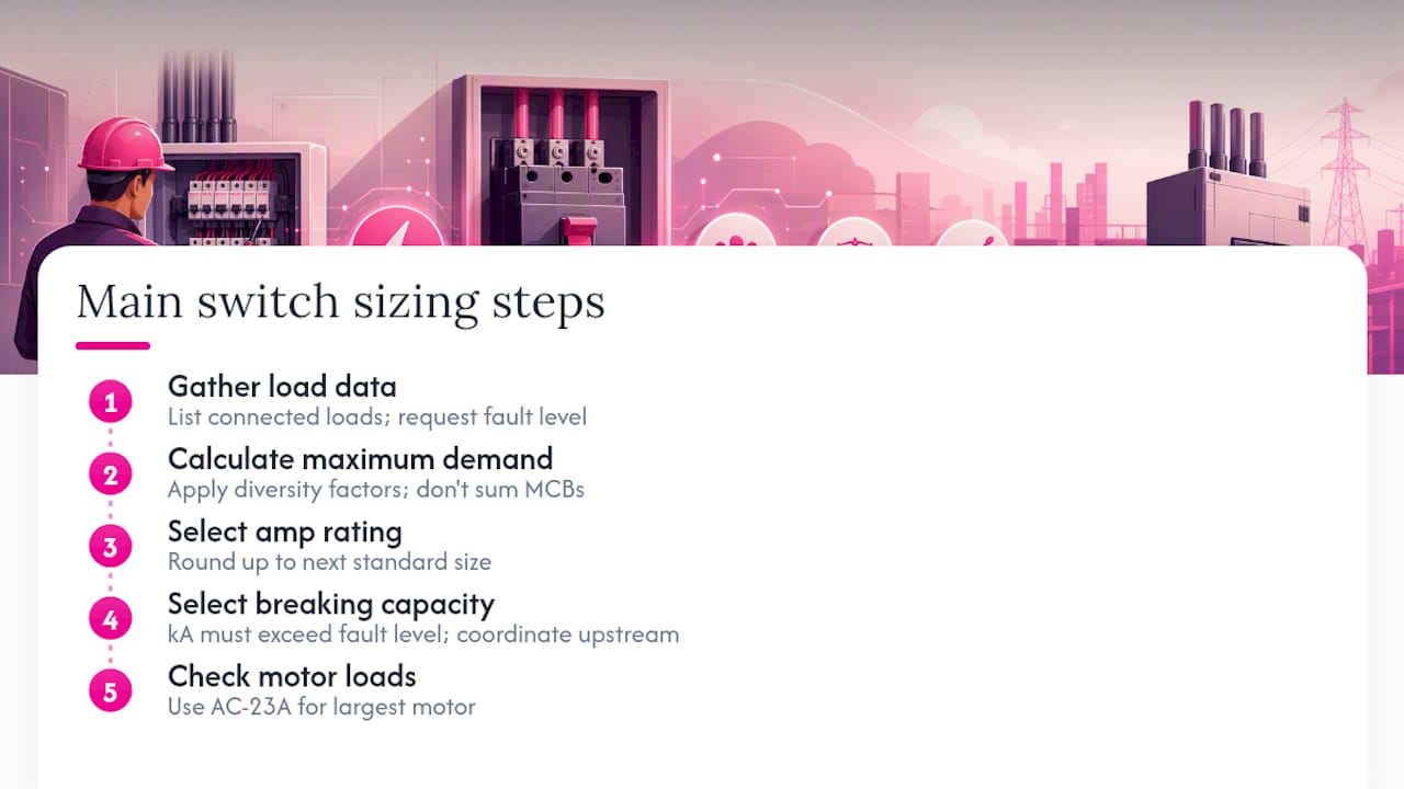
2. Calculate maximum demand. Apply the diversity factors relevant to the load mix rather than summing every circuit breaker on the board. Trade discussion on this exact point is consistent: adding up MCB ratings dramatically overstates real demand and leads to an oversized, more expensive, and sometimes physically incompatible switch.
3. Select the amp rating. Choose a nominal rating at or above the calculated maximum demand, rounding up to the next standard size (63 A, 80 A, 100 A, and so on).
4. Select the breaking capacity. The kA rating must exceed the prospective fault current at that point, and it needs to coordinate with the upstream protective device so faults clear cleanly without the switch itself taking the brunt of the energy. Manufacturer sizing guidance recommends cross-checking against supplier tables rather than assuming a “standard” kA figure will do for every job.
5. Check motor loads separately. If the switch will interrupt motor current under load, confirm it carries an AC-23A rating sized to the largest motor in the group, not just the total connected amps.

Pro Tip: Always request the prospective fault level in writing from the network operator before finalising kA selection. It only takes one phone call, and it removes the guesswork from the riskiest part of the calculation.
Which pole configuration suits your supply type?
Pole configuration follows the supply, not preference. Single-phase consumer mains in many installations use a double-pole main switch, isolating both the active and neutral conductors together. This matters because a fault on the neutral side can still present a shock or fire risk if only the active is switched.
Three-phase supplies need a three-pole (or four-pole, where neutral switching is also required) main switch to isolate all phases simultaneously and maintain balanced protective coordination across the supply. Get the phasing wrong on reconnection and you risk backfeeding or unbalanced loading downstream.
Neutral handling deserves particular attention on older boards, where fused or shared neutrals sometimes turn a straightforward main switch swap into a more involved earthing and bonding review.
Why does AC-23A matter for motor-heavy installations?
AC-23A is the utilisation category that separates a switch built for general isolation from one built to actually break a motor under load. It’s tested to make and break locked-rotor current, the brief but massive current spike a motor draws on startup or when stalled, often several times its running current.
AC-21 and AC-22 categories are rated for resistive and light inductive switching. Neither is designed for the punishment of repeated motor starts and stops. Fit an AC-21 or AC-22 rated switch where AC-23A is actually needed, and the failure mode is predictable: contacts arc, pit and eventually weld shut, turning an isolator into a fire risk rather than a safety device.
Sizing gets genuinely tricky in machine arrays with multiple motors. The switch has to carry the combined thermal load of every motor running together and meet an AC-23A rating matched to the single largest motor in that array, since that’s the worst-case make-and-break event the switch will face. Manufacturer selection guidance shows cases where the largest motor, not the total connected load, is what pushes the designer to the next switch size up. Miss that detail and you end up with a switch that’s thermally fine on paper but mechanically undersized for the job it actually does.
What should a selection and installation checklist cover?
Before signing off on any main switch, work through the following:
- Confirm the prospective fault current at the point of connection, in writing from the network operator where possible.
- Check conductor sizes and upstream protective devices for compatibility with the proposed switch rating.
- Select the correct pole configuration (double-pole for single-phase mains, three or four-pole for three-phase) and confirm the IP rating suits the installation environment.
- Verify discrimination: the switch’s withstand rating needs to coordinate with the protection devices in series so faults clear safely without damaging the switch itself.
- Cross-check the board’s stamped maximum rating before assuming any switch size is physically compatible.
The most frequent errors on real jobs are depressingly consistent: sizing by adding up MCB ratings instead of calculating maximum demand, using an off-load isolator where a load-breaking switch-disconnector is actually required, and underspecifying breaking capacity because nobody asked the network operator for a fault level figure. Underestimating that figure risks welded contacts and dangerous arcing during a genuine fault, because the switch simply can’t clear the energy fast enough.
Documentation matters here too. Main switch circuit breakers sit at the heart of switchboard safety, and installation requires a competent contractor to test and certify the work, not just bolt in a new switch and walk away.
Pro Tip: After installation, test and record the actual trip characteristics against the manufacturer’s datasheet. A switch that passes a visual check can still have thermal or magnetic trip settings that don’t match the load profile you calculated.
What do real-world main switch checks actually look like on-site?
On a mains assessment, we check the switchboard labelling, conductor condition, meter details, and always ask the network operator for the prospective fault current rather than estimating it.
Retrofits throw up the trickiest cases: old boards with fused neutrals, motor retrofits that were never documented, and supply alterations nobody recorded properly. When a board’s stamped rating can’t support the new load, or the wiring condition raises doubt, a switchboard upgrade is the honest recommendation. That’s exactly why a free site inspection for Level 2 work earns its keep. It settles the guesswork before anyone commits to a fix that won’t actually hold up.
Need help sizing or upgrading your main switch?
Getting main switch rating right on paper is one thing. Getting the prospective fault current, the board’s physical limits, and the correct utilisation category all lined up on an actual job is where most DIY sizing attempts fall over. Hdlevel2electriciansydney handles this end to end as a certified Level 2 electrical contractor, from switchboard upgrades and Level 2 metering work through to emergency make-safe callouts when a mains fault can’t wait until business hours.

If you suspect your main switch is undersized, poorly documented, or simply old enough that nobody’s confident in its rating anymore, start with a free site inspection for Level 2 work. We’ll confirm the prospective fault level with the network operator, check your board’s stamped maximum rating, and put the right size and category of switch in writing before any work begins. For jobs that need a full board replacement rather than a straight swap, our switchboard upgrades service covers the compliance side properly, and our Level 2 electrician team handles the network-level connection work that a standard electrician can’t sign off on. Book an inspection and get a written quote before you commit to anything.
What's a Level 2 Contractor's Take on Where Main Switch Sizing Goes Wrong?
Most sizing mistakes aren’t caused by ignorance of the formula. They’re caused by skipping the phone call to the network operator because it feels like an unnecessary delay on a job that’s “obviously” a standard 63 A swap. That single skipped step is where breaking capacity gets underspecified, and it’s rarely the electrician who finds out first. It’s whoever’s standing near the board when a genuine fault occurs.
There’s also a persistent myth that a bigger main switch is always the safer choice. It isn’t. Oversizing the amp rating without checking the board’s stamped maximum, or without confirming the network operator’s service fuse can actually deliver that current, just shifts the failure point somewhere less obvious. A switch rated well above actual demand can also mask an undersized upstream conductor, because nobody’s forced to question whether the wiring behind it can even support the number on the switch label.
The motor switching cases deserve more respect than they usually get, too. Treating AC-23A as a “nice to have” on a machine array with one dominant motor is how contacts end up arcing within months rather than years. If there’s one habit worth adopting industry-wide, it’s this: size for the largest motor’s locked-rotor current first, then check the switch still handles combined thermal load. Doing it the other way around is how switches that look adequate on paper fail on site.
— Christopher
Sources
Related Services
Powering Your Needs with Expertise
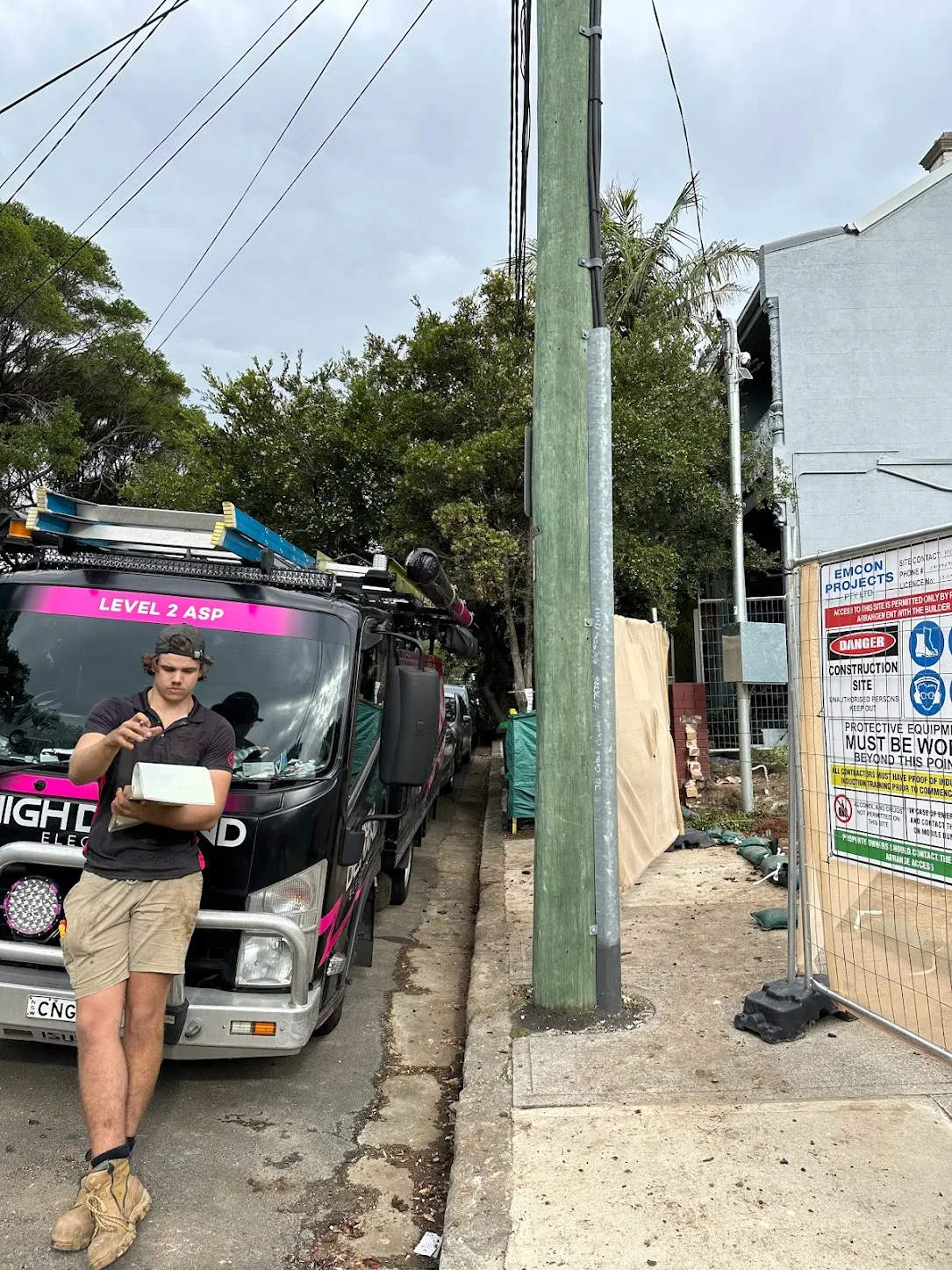
If you’re looking for a reliable, experienced, and prompt electrician, look no further than High Demand Electrical. We cater to all your electrical needs, from routine maintenance to emergency repairs and complete system installations. Our skilled team is committed to providing professional service that ensures your electrical systems run smoothly. Whether it's a small task or a large project, give us a call today. Let us meet all your electrical demands with the quality and reliability you deserve.