EV charger surge protection: what to specify and check
Yes, in almost all Australian EV charger installations you should fit surge protection. Whether you own a single-dwelling wallbox or manage a fleet of DC fast chargers across a commercial site, the case for a dedicated surge protective device (SPD) is backed by IEC standards, DNSP expectations, and the straightforward reality that charger electronics are far more vulnerable to transient voltage spikes than the average household circuit.
Three actions to take right now:
- Check your charger type. AC wallboxes (Level 2, up to 22 kW) need AC-side SPD protection at the consumer unit or dedicated EV board. DC fast chargers additionally require a DC-side SPD between the output terminals and protective earth, as specified under IEC 61851-23:2023.
- Specify the right SPD class. For most residential installs, a Type 2 AC SPD at the consumer unit is the minimum. Commercial and outdoor DC fast-charging sites typically need a two-stage architecture: Type 1 at the service origin plus Type 2 close to the charger, and a DC SPD on the output side.
- Book a licensed Level 2 electrician to confirm earthing impedance, verify lead lengths, and commission the installation with documented records. Earthing resistance above 10 Ω and SPD leads longer than 0.5 m combined are the two most common installation faults that defeat protection before a single surge occurs.
Statistic: IEC 61851-23:2023 sets a voltage protection level (Up) target of ≤ 2.5 kV on DC charger output terminals — a threshold that most charger-integrated suppression components do not independently meet without a dedicated external SPD.
Pro Tip: Fitting an SPD during the initial charger installation costs a fraction of what a post-surge repair or charger replacement does. If your electrician is already at the switchboard, add the SPD to the scope — it is the most cost-effective window you will get.
Key takeaways
EV charger surge protection is a practical necessity in Australia, not a nice-to-have: the combination of outdoor exposure, sensitive charger electronics, and IEC 61851-23:2023’s DC-side Up ≤ 2.5 kV requirement means most installations need at least a Type 2 AC SPD, and DC fast chargers need both AC and DC-side protection.
| Point | Details |
|---|---|
| SPD is required in most cases | IEC 61851-23:2023 mandates DC-side protection; AC-side SPDs are expected under wiring rules for most charger circuits. |
| Match ratings to exposure | Commercial outdoor sites need In ≥ 20 kA and Iimp ≥ 12.5 kA per pole; residential minimums of 5–10 kA are often insufficient. |
| Keep leads under 0.5 m | Combined SPD line and earth lead length must stay under 0.5 m to preserve the device’s rated Up at the charger terminals. |
| Target earthing below 10 Ω | Earthing resistance above 10 Ω defeats the SPD’s ability to divert surge energy safely. |
| Hdlevel2electriciansydney | Certified Level 2 installation with commissioning documentation, SPD selection, and free site inspection across Sydney. |
Table of Contents
- Why EV chargers are uniquely vulnerable to electrical surges
- What standards and regulations apply in Australia?
- Types of surge events that damage EV chargers
- How SPDs protect EV chargers — AC and DC types explained
- Where to fit SPDs in an EV charging installation
- How to choose and specify an SPD for your charger
- Do EV chargers include built-in surge protection?
- Maintenance, testing and replacement of SPDs
- What a Level 2 electrician will assess on site
- An installer’s perspective on what actually goes wrong
- High Demand Electrical: certified Level 2 SPD installation in Sydney
- Sources
Why EV chargers are uniquely vulnerable to electrical surges
EV chargers sit at an uncomfortable intersection of high-power switching, outdoor exposure, and sensitive semiconductor electronics. That combination makes them one of the highest-risk items on any electrical installation for surge-related damage.
Outdoor exposure and lightning proximity. Most residential wallboxes mount on an external wall or in a garage with a long cable run from the switchboard. Commercial chargers are often pole-mounted in open car parks. Both configurations place conductors in positions where induced lightning energy from nearby strikes can couple directly into the supply cables. Australia’s tropical north and eastern seaboard experience some of the highest lightning strike densities in the world, making this a genuine site-specific risk rather than a theoretical one.
Semiconductor sensitivity. Modern EV chargers contain power factor correction circuits, IGBT switching stages, and communication controllers that operate at logic-level voltages. A transient spike lasting just a few microseconds can punch through gate oxide layers in these components. SPDs react to transient events in nanoseconds and protect against microsecond pulses that circuit breakers and fuses simply cannot catch — a breaker operates in milliseconds, which is three orders of magnitude too slow for a lightning-induced transient.
Switching transients from the grid and on-site plant. Utility reclosers, capacitor bank switching, and large motor starts on the same supply network generate repetitive low-energy transients that degrade charger components over time. On commercial sites with multiple chargers, the chargers themselves generate switching noise that can couple back into adjacent units.
- Utility switching and recloser operations: common in suburban and rural Australian networks
- Large motor starts (lifts, air conditioning, compressors) on shared supply
- Internal charger switching reflected back through the supply cable
- Inductive coupling from nearby lightning strikes (no direct strike required)
The 0.5 m lead-length rule. Every metre of SPD connection lead adds inductive voltage during a fast transient. Guidance from TrilPeak highlights that the combined length of the SPD’s line and earth leads must stay under 0.5 m to avoid the inductive voltage drop negating the device’s rated protection level. Exceed that, and the let-through voltage at the charger terminals rises well above the SPD’s published Up value.
Statistic: DC fast chargers operating at higher voltages face greater financial exposure from surge damage — replacement of a DC charger power module typically costs multiples of what a correctly specified SPD costs to supply and install.
What standards and regulations apply in Australia?
Australia does not have a single mandatory national SPD standard that explicitly names EV chargers, but the regulatory picture is clear enough in practice. Three layers of requirement converge on most installations.
International standards that apply on-site:
- IEC 61643-11 (AC SPDs): sets Type 1, Type 2, and Type 3 classification, test waveforms, and key parameters including Up, In, and Iimp. The IEC webstore lists the current edition and related publications — this is the standard your SPD datasheet should reference.
- IEC 61643-31 (DC SPDs): covers DC-side SPD testing and classification, directly relevant to DC fast-charger output protection.
- IEC 61851-23:2023 (DC charging functional requirements): functionally mandates DC-side surge protection and specifies Up ≤ 2.5 kV on DC output terminals.
- AS/NZS 3000 Wiring Rules: the Australian wiring rules do not prescribe SPDs for every circuit, but they do require that installations be safe and that risks be managed. Where a DNSP or AHJ imposes additional requirements for commercial or public charging, those requirements sit on top of AS/NZS 3000.
Who enforces it:
| Standard / Body | Role | What to check on the datasheet |
|---|---|---|
| IEC 61643-11 | AC SPD classification and test | Up (kV), In (kA), Iimp (kA), certification mark |
| IEC 61643-31 | DC SPD classification and test | Up (kV), Imax (kA), modes (+/−/PE) |
| IEC 61851-23:2023 | DC charger functional requirements | Up ≤ 2.5 kV on DC output |
| DNSP / network operator | Connection approval for commercial/public sites | SPD fitted at origin; earthing compliance |
| State electrical safety regulator | Licensing and compliance (NSW: SafeWork NSW) | Licensed Level 2 installer; certificate of compliance |
| Insurer | Policy conditions for commercial assets | Documented commissioning; SPD fitted and recorded |
The risk-acceptance option. Under some wiring-rule frameworks, an owner can formally accept the risk of not fitting an SPD in writing. In practice, most insurers and DNSPs will scrutinise this decision on commercial and public installations. For a residential owner, the financial exposure of an unprotected charger and vehicle electronics makes formal risk acceptance a poor trade-off.
Pro Tip: IEC and AS/NZS wiring rule updates are progressively tightening expectations for SPD use in EV charging installations. Installers working on commercial or public DC fast-charging sites should expect DNSP and insurer scrutiny — document everything at commissioning.
Types of surge events that damage EV chargers
Not all surges are equal, and the type of event determines which SPD class you need and where to put it.
Direct lightning (10/350 µs waveform). A direct strike to a building or nearby structure delivers enormous energy in a 10/350 microsecond waveform. Only a Type 1 SPD, tested to this waveform with a rated Iimp, can handle this energy at the service origin. Residential sites with an overhead service entry in a high-lightning-density area, and any outdoor commercial charging station, should have a Type 1 device at the main switchboard.
Indirect lightning and switching transients (8/20 µs waveform). The far more common event is an induced transient from a nearby strike or a switching operation on the network. These follow an 8/20 µs waveform and are handled by Type 2 devices. A Type 2 SPD mounted close to the charger’s consumer unit or dedicated EV board is the standard minimum for most Australian residential and light-commercial installations.
Internal switching transients. The charger’s own power electronics generate switching noise. On multi-charger commercial sites, this can couple between units. A Type 3 device or device-level suppression at the charger input provides a final layer of protection against these lower-energy, high-repetition events.
Communication-line surges. EV chargers running OCPP over Ethernet or RS-485 have a second vulnerability: transients can enter through data cables and destroy the communication controller without touching the power supply. IEC 61643-21 covers signal-line SPDs — these are mandatory on any commercial charger with external data connections.
- Residential wallbox: indirect lightning and switching transients are the primary risk; Type 2 AC SPD at consumer unit is the standard response.
- Workplace multi-charger site: add Type 1 at the main incomer if overhead supply; signal-line SPDs on OCPP data cables.
- Highway DC fast charger: highest exposure; two-stage AC protection (Type 1 + Type 2) plus DC-side SPD on output terminals; signal-line protection on all data ports.
How SPDs protect EV chargers — AC and DC types explained
An SPD does not block a surge. It acts as a high-speed safety valve: when voltage rises above a set threshold, the device conducts and diverts the excess energy to protective earth in nanoseconds. The charger sees only the clamped residual voltage, which is the device’s voltage protection level (Up).
Type 1 SPDs are tested with the 10/350 µs direct-lightning waveform. They carry a rated Iimp (impulse current) and are fitted at the service origin or main switchboard. Required on sites with overhead supply or high lightning exposure.
Type 2 SPDs are tested with the 8/20 µs waveform and carry a rated In (nominal discharge current) and Imax (maximum discharge current). These are the workhorses of EV charger protection, mounted at the consumer unit, dedicated EV board, or charger input. The Bourns application note recommends In ≥ 20 kA and Iimp ≥ 12.5 kA per pole for outdoor commercial stations — residential-grade SPDs with In of 5–10 kA are often insufficient for these sites.
Type 3 SPDs are low-energy devices for final protection at the equipment terminals. They supplement, not replace, upstream Type 1 or Type 2 devices.
DC SPDs protect the output terminals of DC fast chargers. They are tested per IEC 61643-31 and must cover the (+), (−), and PE modes. Up ≤ 2.5 kV is the target per IEC 61851-23:2023.
Key datasheet parameters to read:
- Up (voltage protection level, kV): the clamped voltage the charger will see during a surge. Lower is better.
- In (nominal discharge current, kA): the 8/20 µs current the device handles repeatedly without degradation.
- Iimp (impulse current, kA): the 10/350 µs current for Type 1 devices.
- Imax (maximum discharge current, kA): the single-event maximum for Type 2 devices.
- Uc (continuous operating voltage, V): must exceed the supply voltage with margin.
- Response time (ns): how fast the device clamps.
- Modes: L–N, L–PE, N–PE for AC; (+)/PE and (−)/PE for DC.
| SPD type | In / Iimp | Up target | Protection modes | AC / DC | Mounting | IP rating | End-of-life indicator |
|---|---|---|---|---|---|---|---|
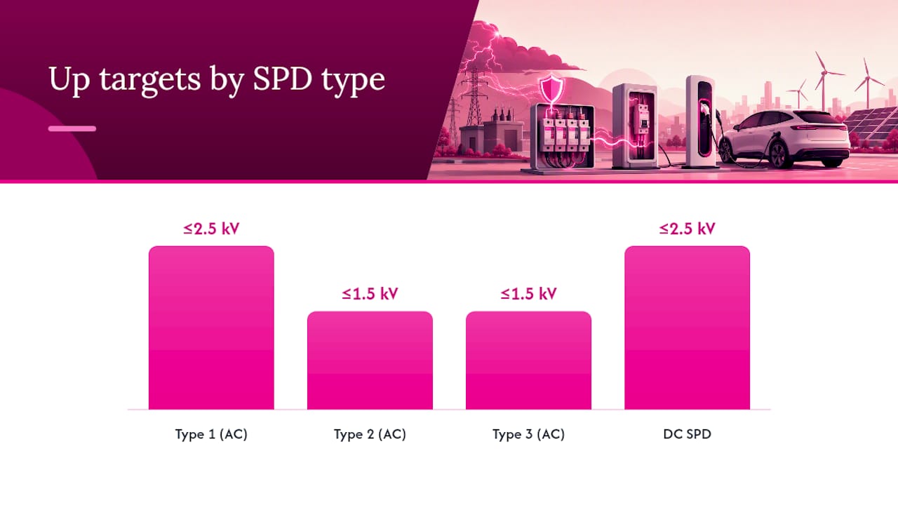
| Type 1 (AC) | Iimp ≥ 12.5 kA/pole | ≤ 2.5 kV | L–N, L–PE, N–PE | AC input | DIN-rail, main board | IP20 minimum | Visual window / remote contact |
| Type 2 (AC) | nominal discharge current rating appropriate to commercial exposure | voltage protection level 1.5 kV or below | L–N, L–PE, N–PE | AC input | DIN-rail, EV board | IP20 minimum | Visual window / remote contact |
| Type 3 (AC) | lower energy rating for equipment-level protection | voltage protection level 1.5 kV or below | L–N, L–PE | AC, equipment level | Panel or plug-in | IP20 | Visual indicator |
| DC SPD | Imax ≥ 20 kA | ≤ 2.5 kV | (+)/PE, (−)/PE | DC output | DIN-rail, charger enclosure | IP54+ (outdoor) | Visual window / remote contact |
Remote signalling. Commercial installations should specify SPDs with a dry-contact remote alarm output. This allows the building management system or OCPP back-end to receive an alert when the SPD reaches end of life, so the device is replaced before the next surge event rather than after.
Where to fit SPDs in an EV charging installation
Placement determines whether your SPD actually protects the charger or just looks like it does. The two most common installation errors are fitting the SPD too far from the charger and using leads that are too long.
Location options, from supply origin to charger:
- Main switchboard / service origin. A Type 1 SPD here handles direct-lightning energy before it reaches any downstream equipment. Required on sites with overhead supply entry or high lightning exposure. This device protects the whole installation, not just the charger.
- Submain distribution board feeding the charger. A Type 2 SPD at this point protects the charger circuit and any other loads on the sub-board. Practical for strata buildings where the main switchboard is shared and a dedicated sub-board feeds the EV charging area.
- Dedicated EV consumer unit. The most common solution for residential EV charger installations where the main consumer unit lacks spare ways. A pre-wired Type 2 SPD in a dedicated EV unit keeps lead lengths short and the installation tidy.
- Inside the charger enclosure. Some chargers accept a DIN-rail SPD inside the enclosure. Only do this if the enclosure is rated for the SPD’s IP class and the manufacturer’s warranty is not voided. Verify on the charger datasheet.
- DC-side SPD for DC fast chargers. Mounted between the DC output terminals and protective earth inside the charger cabinet. This is a separate device from the AC-input SPD and is required by IEC 61851-23:2023. Commercial EV charger installations at highway or workplace sites need both AC and DC SPDs.
The 0.5 m combined lead-length rule in practice. Measure the total loop: line lead from the busbar to the SPD terminal, plus earth lead from the SPD to the earth bar. That combined length must stay under 0.5 m. Use V-wiring (Kelvin topology) where the SPD taps off the supply conductor rather than being wired in series, to minimise inductive drop.
Earthing requirements. Target earthing resistance below 10 Ω at the charger location. Equipotential bonding between the charger enclosure, any metal conduit, and the main earth bar is not optional — a high-impedance earth path defeats the SPD’s ability to divert surge energy safely.
Site examples:
- Single-dwelling Level 2 wallbox: Type 2 SPD in dedicated EV consumer unit, 0.5 m leads, earthing resistance confirmed < 10 Ω.
- Strata building with central switchboard: Type 2 SPD in sub-board feeding the apartment EV charging area; remote contact wired to building management system.
- Workplace with multiple AC chargers: Type 1 at main incomer (if overhead supply), Type 2 at each charger sub-board, signal-line SPDs on OCPP Ethernet ports.
- Public DC fast charger: Two-stage AC protection (Type 1 + Type 2) at the charger’s AC input, DC SPD on output terminals, IP54-rated enclosures, remote contact to network operations centre.
Commissioning checklist for electricians:
- Photograph SPD installation showing lead routing and lengths.
- Record SPD make, model, serial number, and datasheet Up/In/Iimp values.
- Measure and record earthing resistance at the charger location.
- Test remote dry-contact output and confirm alarm receipt at BMS or OCPP back-end.
- Label SPD with installation date and next inspection date.
- Include all records in the commissioning certificate handed to the property manager or owner.
How to choose and specify an SPD for your charger
Specifying the wrong SPD is almost as bad as fitting none at all. Work through these steps before ordering anything.
Step 1: Determine charger class and fault current. Is it an AC wallbox (single-phase or three-phase) or a DC fast charger? What is the prospective fault current at the installation point? This sets the minimum Iimp and In values. Use the EV charger load calculator to confirm supply capacity and breaker sizing before specifying the SPD.
Step 2: Assess exposure level.
- Residential, underground supply, low lightning density: Type 2 AC SPD, In ≥ 10 kA.
- Residential, overhead supply or high lightning density: Type 1 at origin + Type 2 at charger.
- Commercial outdoor or highway DC fast charger: Type 1 + Type 2 AC, DC SPD, In ≥ 20 kA, Iimp ≥ 12.5 kA per pole per the Bourns guidance.
Step 3: Set Up targets. For AC-side protection, target Up ≤ 1.5 kV. For DC-side protection on fast chargers, target Up ≤ 2.5 kV per IEC 61851-23:2023.
Step 4: Check mechanical and environmental fit.
- IP rating: IP20 minimum for indoor switchboard; IP54 or better for outdoor or exposed locations.
- Operating temperature: confirm the device’s rated range covers Australian summer conditions (up to 50°C in some locations).
- Mounting: DIN-rail for consumer units and sub-boards; panel-mount for charger enclosures.
- Consumer unit capacity: confirm spare ways exist, or plan a switchboard upgrade or dedicated EV board.
Step 5: Specify monitoring and lifecycle features.
- Remote dry-contact alarm output for commercial sites.
- Visual end-of-life indicator (colour window) for all sites.
- Replaceable cartridge design so the base stays wired and only the cartridge is swapped at end of life.
- Confirm warranty period and expected service life from the manufacturer datasheet.
Step 6: Coordination checks.
- Upstream overcurrent device must be sized to back-up the SPD per the manufacturer’s requirement.
- Confirm earthing impedance meets the < 10 Ω target.
- Specify signal-line SPDs (IEC 61643-21) for all external data connections (Ethernet, RS-485).
- Notify DNSP where required for commercial or public installations.
Procurement quick-check — request these values from the supplier:
- Up (kV), In (kA), Iimp (kA), Imax (kA), Uc (V)
- Certification marks: IEC 61643-11 (AC) or IEC 61643-31 (DC), CE, TÜV where applicable
- Remote contact specification (voltage, current rating)
- IP rating and operating temperature range
Pro Tip: Manufacturers like DEHN, Bourns, and Phoenix Contact publish application notes specifically for EV charging SPD selection. Download the relevant note before specifying — it will give you the exact In and Iimp values recommended for your charger class and exposure level, and it is the document your DNSP or insurer may ask to see.
Do EV chargers include built-in surge protection?
Many chargers advertise “built-in surge protection,” and most do include some form of internal suppression. The honest answer is that this rarely replaces a supply-side SPD for compliance or reliable protection.
What built-in protection typically covers. Internal MOV (metal oxide varistor) components or TVS diodes provide local clamping at the charger’s input terminals. These are low-capacity devices designed to handle repetitive low-energy transients from the supply, not the high-energy events a Type 1 or Type 2 SPD is rated for.
What it does not cover:
- High-energy direct or indirect lightning events that exceed the internal component’s Imax rating (typically well below the 20 kA recommended for commercial outdoor sites).
- DC-side protection on fast chargers — internal AC-input suppression does not protect the DC output terminals or the vehicle’s onboard electronics.
- Remote signalling: built-in components have no end-of-life indicator or alarm output.
- The lead-length problem still applies: if the charger is at the end of a long cable run from the switchboard, the transient energy arriving at the charger terminals may already exceed what the internal device can handle.
What electricians should verify on the charger datasheet:
- Is an internal SPD declared? If so, what is its rated Up and Imax?
- Does the manufacturer’s warranty require an external SPD to remain valid?
- Does the charger carry IEC 61851-23:2023 compliance documentation covering DC-side protection?
For Tesla EV charger installations and other premium wallboxes, check the manufacturer’s installation guide directly — some specify that an external Type 2 SPD is required at the consumer unit as a warranty condition. The IPD guidance for Australian installers reinforces this: fitting an external SPD at the consumer unit or dedicated EV board is the standard practice regardless of what the charger claims internally.
Maintenance, testing and replacement of SPDs
An SPD that has absorbed a significant surge event may look intact but be degraded or failed. A maintenance programme is not optional on commercial sites.
Routine checks:
- Monthly: check the visual end-of-life indicator (colour window) on each SPD. A failed indicator means the device needs immediate replacement.
- Monthly: verify the remote dry-contact alarm is live and reporting correctly to the BMS or OCPP back-end.
- After any known surge event or storm: inspect all SPDs visually and test remote contacts before returning chargers to service.
Annual inspection:
- Functional check of all SPD remote contacts.
- Visual inspection of lead routing and lengths (confirm leads have not been disturbed during other maintenance).
- Review service log for any alarm events since the last inspection.
- Confirm earthing resistance is still below 10 Ω.
Replacement triggers:
- Visual end-of-life indicator has changed state.
- Remote contact alarm has fired.
- A significant surge event has occurred (lightning strike to or near the site).
- The device has reached the manufacturer’s stated service life (check the datasheet — typically 10–20 years for quality devices, but this varies).
What to log at commissioning and after service:
- SPD make, model, serial number, and datasheet snapshot (Up, In, Iimp, Uc).
- Installation date and lead length measurements.
- Earthing resistance reading.
- Remote contact wiring test result.
- Installation photographs.
- Any subsequent replacement dates and the reason for replacement.
What a Level 2 electrician will assess on site
A qualified Level 2 electrician does more than bolt an SPD to a DIN rail. The site assessment is where the protection strategy is confirmed and the documentation that matters to insurers and DNSPs is created.
Step-by-step assessment:
- Photograph the existing switchboard, consumer unit, and proposed charger location before any work begins.
- Check switchboard labelling and confirm the supply origin SPD status (fitted, type, condition, or absent).
- Measure earthing resistance at the charger location and at the main earth bar.
- Confirm consumer unit capacity for the SPD and charger circuit, or identify the need for a dedicated EV board or switchboard upgrade.
- Measure proposed SPD lead run lengths and confirm the 0.5 m combined limit is achievable.
- Check equipotential bonding between charger enclosure, conduit, and earth bar.
- Verify OCPP or RS-485 data cable routing and identify signal-line SPD requirements.
- Confirm DNSP notification requirements for the installation class.
What the electrician provides at handover:
- Commissioning certificate with all test results.
- Datasheet pack for every SPD fitted (make, model, Up, In, Iimp, Uc, certification marks).
- Labelled SPDs with installation date and next inspection date.
- Operational briefing for the property manager covering visual indicator checks and what to do after a surge event.
- Written record of earthing resistance, lead lengths, and remote contact test results.
These records matter. An insurer assessing a surge-damage claim will ask for the commissioning certificate. A DNSP auditing a commercial installation will ask for the SPD datasheet and earthing test result. Having them ready is the difference between a straightforward claim and a disputed one.
Pro Tip: Before the site visit, have the charger’s installation manual and datasheet ready, along with any existing switchboard single-line diagram. This cuts commissioning time and reduces costs — the electrician can confirm SPD compatibility and lead-length options before arriving on site.
An installer’s perspective on what actually goes wrong
The most common site surprise is not a missing SPD — it is an SPD that was fitted but wired with leads that are 800 mm or longer combined, which effectively cancels the device’s rated protection level during a fast transient. On a recent commercial site assessment, the SPD was present, correctly rated, and even had a remote contact wired to the BMS. But the installer had looped the earth lead around the back of the consumer unit to reach the earth bar, adding nearly 600 mm to the loop. The charger was unprotected in any meaningful sense.
The fix is straightforward: plan the SPD position before the consumer unit is wired, not after. Mount the SPD on the DIN rail closest to the earth bar, use the shortest possible leads, and photograph the final installation before closing the enclosure. If the lead lengths cannot be kept under 0.5 m in the existing consumer unit, fit a dedicated EV board positioned closer to the charger or the earth bar.
The earthing check is the other step that gets skipped under time pressure. A quick earth loop impedance test at the charger location takes five minutes and gives you the number that goes on the commissioning certificate. If it comes back above 10 Ω, you have a bonding problem to fix before the SPD can do its job.
High Demand Electrical: certified Level 2 SPD installation in Sydney
Surge protection for an EV charger is only as good as the installation behind it. Hdlevel2electriciansydney delivers certified Level 2 EV charger surge protection and full commissioning documentation — the records your insurer and DNSP will ask for.
Our team handles the complete scope: SPD selection matched to your charger class and exposure level, lead-length verification, earthing resistance testing, and a commissioning certificate with datasheet pack at handover. Services include residential and commercial EV charger installation, surge protection installation, switchboard upgrades, emergency make-safe, and strata EV board installations across Sydney. Free site inspections are available for Level 2 work.
Call us or book online to arrange your site inspection. A licensed Level 2 electrician will assess your installation, specify the right SPD, and hand over the documentation you need — rain, hail, or shine.
Sources
Standards and regulatory references:
- EV Charger Surge Protection: Is It Required by IEC/NEC? 2026 Rules
- Understanding EV Charging Protection: Why surge protection is essential for EV charging stations
- IEC webstore publication (IEC standards)
- How to choose the right SPD for EV charging systems (Bourns app note)
- The Importance of Surge Protection for EV Chargers (IPD)
Manufacturer application notes and installer guidance:
Recommended
Powering Your Needs with Expertise
If you’re looking for a reliable, experienced, and prompt electrician, look no further than High Demand Electrical. We cater to all your electrical needs, from routine maintenance to emergency repairs and complete system installations. Our skilled team is committed to providing professional service that ensures your electrical systems run smoothly. Whether it's a small task or a large project, give us a call today. Let us meet all your electrical demands with the quality and reliability you deserve.