Fault Loop Impedance Calculator
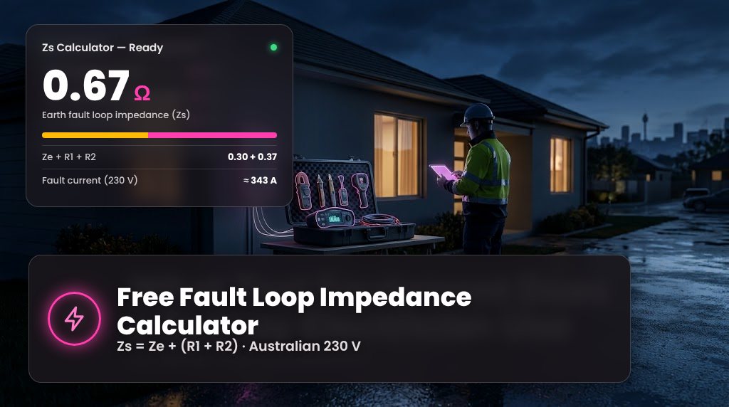
Earth Fault Loop Impedance (Zs) Calculator
Results update as you type. Nothing you enter is stored or sent anywhere.
Measured or obtained at the main switchboard
Conductor temperature correction optional
R1 and R2 measured cold (dead test) are lower than they will be when the cable is carrying load. Tick to scale R1 + R2 to a conductor temperature you choose. Ze is not adjusted.
Use the rated operating temperature of the cable insulation
Enter the reading from your loop impedance tester, at the furthest point of the circuit
Compare with a protective device optional
The tool won't guess device data. Enter the current (Ia) that operates your device within the required disconnection time, taken from the manufacturer's time-current curve or the applicable table, and it will show the matching reference impedance U₀ ÷ Ia.
Required for the comparison
What Is Fault Loop Impedance?
Earth fault loop impedance (Zs) is the total opposition to current along the path a fault takes when an active conductor touches earthed metal. It is measured in ohms (Ω).
In a typical Australian MEN (multiple earthed neutral) installation, fault current flows from the supply transformer along the active conductor to the fault, back through the circuit's protective earth conductor to the main earthing terminal, across the MEN link to the neutral, and home to the transformer through the network neutral.
Every part of that loop adds impedance. The lower the total, the more current flows during a fault. That current is what makes a circuit breaker or fuse operate and cut the supply before exposed metal stays at a dangerous voltage. This is called automatic disconnection of supply.
If the loop impedance is too high, fault current may be too low to operate the protective device quickly enough, leaving metal parts live for longer than the Wiring Rules allow.
Understanding Ze, Zs, R1 and R2
The total loop is split into the part outside the installation, which you can't change, and the circuit conductors, which you can.
The impedance of the supply side of the loop: transformer, network active and neutral, service and consumer mains up to the main earthing point. Measured at the main switchboard.
The resistance of the circuit's active conductor from the protective device to the furthest point of the circuit.
The resistance of the circuit's protective earthing conductor from that same point back to the earth bar. Often higher than R1 where a smaller earth is used.
The whole loop for that circuit: Ze plus R1 plus R2. This is the value that decides the prospective earth fault current at the end of the circuit.
R1 and R2 are usually measured together as R1 + R2 during a dead test, by linking the active and earth at one end and measuring between them at the other. Ze stays the same for every circuit at the switchboard, so in practice a high Zs on one circuit is almost always caused by its R1 + R2: a long run, a small earth conductor or a poor connection.
Fault Loop Impedance Formula
Add the external impedance to the resistance of the circuit's active and protective earth conductors. This simple sum treats every term as resistive, which is a sound approximation for typical final subcircuits where cable reactance is small.
For large cables or long submains, reactance becomes significant and a full vector calculation, or a measurement, gives a more accurate Zs.
Worked example (illustrative values)
- Ze at the main switchboard: 0.30 Ω.
- 25 m of 2.5 mm² copper, active and earth the same size. At about 7.41 Ω/km at 20 °C, R1 ≈ R2 ≈ 0.185 Ω, so R1 + R2 = 0.37 Ω.
- Zs = 0.30 + 0.37 = 0.67 Ω. If = 230 ÷ 0.67 ≈ 343 A.
- Corrected to 75 °C: R1 + R2 = 0.37 × 1.216 ≈ 0.45 Ω, so Zs ≈ 0.75 Ω and If ≈ 307 A.
- Compare with the device: if verified data shows a breaker needs 200 A to trip in the required time, the reference is 230 ÷ 200 = 1.15 Ω, so this circuit sits below it.
Being under a reference value tells you something about fault current only. Compliance also depends on the disconnection time, the device, the installation and the full set of verification tests.
Why Is Fault Loop Impedance Testing Important?
- It proves the earth fault path works. Continuity tests show a conductor is connected. A loop test shows the whole path, supply included, can carry enough current.
- It confirms enough fault current can flow. Breakers and fuses need a minimum current to operate within a set time. Zs determines whether that current is available.
- It underpins automatic disconnection. AS/NZS 3000 relies on fast disconnection to limit how long exposed metal can stay at a dangerous touch voltage.
- It catches what a visual check can't. Loose terminations, undersized earths, damaged cables and long runs all show up as a higher than expected Zs.
Calculation, measurement, verification and compliance are not the same
- Calculation: an estimate from design data or test readings, like this tool.
- Measurement: a reading from a loop impedance tester on the actual circuit.
- Verification: the inspection and testing an electrician carries out under AS/NZS 3000 Section 8, with guidance in AS/NZS 3017.
- Compliance: a licensed electrician's judgement that the installation meets every applicable requirement, recorded on the relevant certificate.
Fault Loop Impedance vs Prospective Fault Current
Prospective earth fault current is the nominal phase-to-earth voltage divided by the loop impedance. Halve the impedance and the fault current doubles. At 230 V, a Zs of 1.0 Ω gives about 230 A, and 0.5 Ω gives about 460 A.
This is an estimate of the current that would flow for a fault of negligible impedance. Real faults often have some resistance of their own, and actual supply voltage varies, so the true current can be lower.
Earth fault current vs short-circuit current
Prospective earth fault current (PEFC) flows from active to earth and uses the protective earth conductor as its return path. It is the value that matters for automatic disconnection and is calculated from Zs.
Prospective short-circuit current (PSCC) flows from active to neutral, or between phases, and is usually higher. It matters for the breaking capacity of switchgear, not for earth fault protection.
A competent test records both and uses the higher figure when checking that protective devices can safely interrupt a fault.
Common Factors Affecting Fault Loop Impedance
| Factor | Effect on Zs |
|---|---|
| Cable length | Resistance rises in proportion to length. Doubling a run roughly doubles R1 + R2. |
| Conductor size | Larger cross-sections have lower resistance. A reduced-size earth raises R2 even when the active is generous. |
| Conductor material | Aluminium has about 1.6 times the resistance of copper for the same size. |
| Conductor temperature | Hot conductors have higher resistance, so a cold test reading understates Zs in service. |
| Connection quality | Loose, corroded or overheated terminations add resistance and can make readings unstable. |
| Earthing system | The MEN link, main earthing conductor and their connections all form part of the loop. |
| External supply impedance | Ze depends on transformer size, distance from the transformer and the network and service cables. It differs from site to site. |
| Protective conductor condition | A damaged, undersized or broken earth conductor raises R2 or removes the low-impedance path altogether. |
Fault Loop Impedance FAQs
What is a fault loop impedance calculator?
It's a tool that adds the external loop impedance (Ze) to the circuit conductor resistances (R1 + R2) to estimate total earth fault loop impedance (Zs), then works out the prospective earth fault current. This one can also assess a measured Zs and compare it with device data you enter.
How do you calculate earth fault loop impedance?
Use Zs = Ze + (R1 + R2). For example, Ze of 0.30 Ω plus R1 + R2 of 0.37 Ω gives a Zs of 0.67 Ω. Correct R1 + R2 for conductor operating temperature if the readings were taken cold.
What is the difference between Ze and Zs?
Ze is the external part of the loop, from the supply transformer to the installation's main earth. Zs is the total loop for a particular circuit, Ze plus that circuit's R1 + R2. Ze is the same for every circuit at a switchboard, while Zs differs circuit by circuit.
What are R1 and R2?
R1 is the resistance of the circuit's active conductor and R2 is the resistance of its protective earth conductor, both measured from the switchboard to the furthest point of the circuit. They're usually measured together as R1 + R2 during dead testing.
What is an acceptable earth fault loop impedance?
There's no single acceptable value. The maximum depends on the protective device type and rating, its time-current characteristics, the nominal voltage and the required disconnection time. In general the limit is the voltage divided by the current that operates the device within that time (U₀ ÷ Ia). Check against AS/NZS 3000 and the manufacturer's data for the device you've installed.
Why is fault loop impedance testing important?
It confirms the earth fault path can carry enough current to operate the protective device quickly, so exposed metal doesn't stay live during a fault. It also picks up loose connections and undersized or damaged earth conductors.
What happens if earth fault loop impedance is too high?
Fault current may be too low to trip the circuit breaker or blow the fuse within the required time, so metal parts can stay at a dangerous voltage. Fixes include shortening the run, increasing conductor or earth size, repairing connections, changing the protective device or adding RCD protection where the standard permits. A licensed electrician should find the cause.
How do you calculate prospective earth fault current?
Divide the nominal voltage by the loop impedance: If = U₀ ÷ Zs. At 230 V with a Zs of 0.75 Ω, that's about 307 A. Treat it as an estimate. A fault with its own resistance, or a lower supply voltage, gives less current.
Does cable length affect earth fault loop impedance?
Yes. Conductor resistance rises in direct proportion to length, so longer runs increase R1 + R2 and therefore Zs. Long runs on small cables are the most common reason a circuit's Zs is too high.
What is the relationship between Zs and automatic disconnection?
Automatic disconnection relies on enough fault current to operate the protective device within a set time. AS/NZS 3000 sets maximum disconnection times, typically 0.4 s for final subcircuits supplying socket-outlets or hand-held and portable equipment, and up to 5 s for submains and circuits supplying fixed equipment, subject to the conditions in the standard. Lower Zs means higher fault current and faster operation.
Can a calculated Zs replace an actual impedance test?
No. A calculated Zs is useful for design and for checking dead-test readings, but it relies on assumed values. The installation must still be inspected and tested by a licensed electrician to AS/NZS 3000 Section 8, using AS/NZS 3017 as guidance.
Need Professional Electrical Testing or Verification?
High Demand Electrical is a Level 2 ASP accredited contractor in Sydney. Our licensed electricians test, verify and fix installations, from a single circuit with a high loop reading to a full switchboard upgrade.
More free electrical tools
Powering Your Needs with Expertise
If you’re looking for a reliable, experienced, and prompt electrician, look no further than High Demand Electrical. We cater to all your electrical needs, from routine maintenance to emergency repairs and complete system installations. Our skilled team is committed to providing professional service that ensures your electrical systems run smoothly. Whether it's a small task or a large project, give us a call today. Let us meet all your electrical demands with the quality and reliability you deserve.

Licensed Level 2 ASP electricians across Sydney. Same-day service and 24/7 emergency response.
and Quick to Respond!
Licence 397193C
ABN 87 051 836 527