60 A Breaker, Earth Assurance: Gen 3 Tesla Wall Connector In Australia
A compliant Tesla Gen 3 Wall Connector installation needs a 230 V single‑phase or supported three‑phase supply, typically protected by a 60 A double‑pole breaker sized against continuous‑load rules, terminated with correctly sized copper conductors, and connected to a permanent, tested earth path. Commissioning through the Tesla One app, using the unit’s QR code and a 2.4 GHz Wi‑Fi connection, is mandatory before the charger will register to its owner or unlock full functionality.
TL;DR:
- The maximum circuit breaker size for a Tesla Gen 3 Wall Connector installed in Australia is 60 A double-pole, but lower ratings like 32 A may be suitable for homes with limited supply or to simplify installation.
- Copper conductors between 4 mm² and 25 mm² are required, with size dependents on breaker rating, cable length, and installation method; aluminium conductors are not accepted.
- The Wall Connector must be connected to a permanent earth path that passes internal testing; earth path issues are a common cause of lockouts and should be verified with impedance testing.
- Single-phase supply generally caps output around 13.8 kW at 60 A, while three-phase setups can deliver up to 22 kW, requiring existing three-phase power or an upgrade for faster charging.
- Proper commissioning via the Tesla One app, including QR code setup, Wi-Fi connection, and power sharing configuration, is mandatory to enable full functionality and remote diagnostics.
Table of Contents
- What are the Tesla Wall Connector requirements for circuit breaker size?
- What wire size and terminals does a Tesla Wall Connector need?
- Why does a Tesla Wall Connector need a dedicated earth?
- Can a Tesla Wall Connector deliver 22kW at home?
- How do you commission a Tesla Wall Connector after installation?
- Where should a Tesla Wall Connector be mounted?
- What are the requirements for installing multiple Wall Connectors?
- What qualifications does a Tesla Wall Connector installer need?
- What surprises come up on real Tesla Wall Connector jobs?
- Book a free site inspection with High Demand Electrical
- Key manuals and support pages to keep on hand
- Sources
- FAQ
What are the Tesla Wall Connector requirements for circuit breaker size?
Tesla specifies a double‑pole 60 A circuit breaker to reach maximum single‑phase output on the Gen 3 J1772 Wall Connector. That figure isn’t arbitrary. It reflects the maximum current the Wall Connector can draw on a single‑phase circuit, plus the margin every properly designed circuit needs against continuous load.
Continuous‑load derating is the part installers get wrong most often on EV projects. AS/NZS 3000 treats EV charging as a continuous load, meaning the circuit has to be rated for sustained current draw over hours, not the brief peaks a toaster or kettle pulls. A breaker sized right at the equipment’s maximum draw with no margin will nuisance‑trip under real charging conditions, especially on hot days when thermal derating kicks in.
Temperature matters more in Australian installations than most people expect. A Wall Connector mounted on an exterior north‑facing wall in Western Sydney summer, inside a switchboard enclosure that also houses other high‑draw circuits, needs breaker and conductor sizing that accounts for ambient heat, not just rated current. Cable bunched tightly in conduit with other circuits derates further again.
A smaller breaker is sometimes the right call, not a compromise:
- Where the property’s supply capacity is limited (a small single‑phase connection already carrying air conditioning, an electric hot water system and cooking loads).
- Where the switchboard has no spare capacity for a 60 A EV circuit without upgrading the main supply.
- Where the owner is happy trading charge speed for a simpler, cheaper install, since a 32 A circuit still delivers meaningful overnight charging.
Dropping to a 32 A breaker roughly halves the charging rate compared with 60 A, but it also halves the conductor size needed and often avoids a switchboard upgrade entirely. For most home charging patterns, where the car sits overnight for eight or more hours, the lower rate still fully charges a typical Tesla battery from a partial state.
The Wall Connector’s own integrated RCD Type A + DC 6 mA changes how upstream protection should be configured. Older switchboards sometimes have upstream RCDs that aren’t rated for DC leakage current, which EV chargers can introduce during charging. Because the unit already carries its own Type A RCD with 6 mA DC sensitivity, installers need to check whether the upstream RCD is a compatible type or whether it risks nuisance tripping from double protection, rather than assuming any old safety switch will do. Getting this interaction wrong is one of the more common causes of intermittent charging faults on otherwise correctly wired installs.
What wire size and terminals does a Tesla Wall Connector need?
The wirebox terminals on the Gen 3 Wall Connector accept stranded copper conductors between 4 mm² and 25 mm², or solid copper conductors from 1.5 mm² up to 25 mm², according to the Gen 3 installation manual for Australia and New Zealand. Copper is not optional. Aluminium conductors are not accepted, a detail worth flagging early if you’re planning a long run where aluminium might otherwise look tempting on cost.
Picking the right size inside that range comes down to two variables working together: the breaker’s amperage and the distance from switchboard to Wall Connector. A short 10‑metre run on a 32 A circuit tolerates a smaller conductor than a 40‑metre run on a 60 A circuit, where voltage drop and heat both increase with length.
- Confirm the breaker rating first. A 32 A circuit and a 60 A circuit call for genuinely different conductor sizes, so lock in the breaker choice before ordering cable.
- Measure the actual run length, not a rough guess, including vertical drops through walls and any conduit detours around existing services.
- Apply local cable sizing tables from AS/NZS 3000, factoring in installation method (conduit, buried, in wall cavity) and grouping with other circuits.
- Check the result sits inside the terminal’s accepted range of 4 to 25 mm² stranded or 1.5 to 25 mm² solid, and confirm ferrule compatibility if using stranded cable.
- Verify the neutral and earth conductors are sized to match, since undersizing either one undermines the whole circuit’s protection.
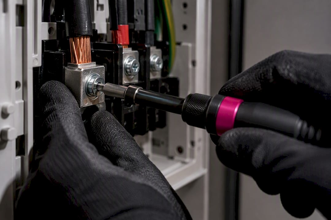
Stranded copper terminated directly into a torque‑rated terminal without a ferrule is a common shortcut that causes problems later. Individual strands can spread, miss full contact with the terminal, or work loose under thermal cycling as the connection heats and cools daily. Ferrules crimp the strands into a solid, uniform contact point that holds torque properly and resists loosening over years of use.
Pro Tip: Always torque wirebox terminals to the exact value listed in the Tesla installation manual for your terminal size, and check it again after the first few charging cycles. Copper conductors settle slightly under initial thermal cycling, and a terminal that felt correctly torqued on day one can read slightly loose a fortnight later.
A loose termination is more than an inconvenience. It creates a high‑resistance connection that generates heat under load, which is exactly the failure mode that causes scorched terminals, melted insulation, and in worst cases a fire risk inside the wirebox. Following the manual’s torque specification isn’t a bureaucratic checkbox, it’s the single cheapest insurance against a preventable fault.
Why does a Tesla Wall Connector need a dedicated earth?
The Wall Connector requires a permanent earth path back to the main equipment earthing point, and it will refuse to charge if that path fails an internal earth assurance test, according to the global Gen 3 installation manual. This isn’t a soft warning. It’s a hard lockout the unit enforces on its own, independent of the breaker or upstream RCD.
Earth assurance testing works by continuously monitoring the integrity of the earth connection while the vehicle is plugged in. If resistance climbs above the safe threshold, the unit stops charging rather than continuing on a compromised path. For most Australian homes running a standard TN‑type supply, earth assurance stays enabled and active by design.
The supply type actually matters here more than most installers initially assume:
- TN grids (the vast majority of Australian residential supplies) keep earth assurance active, and the Wall Connector expects a solid bonded connection to the main earthing point.
- TT and IT grids, less common in Australian residential settings but occasionally found in specific industrial or rural configurations, may have earth assurance disabled per the manufacturer’s guidance, since the earthing topology behaves differently.
- Mixed or unusual configurations, such as properties with private power poles or older PME (protective multiple earthing) arrangements, deserve a dedicated check before assuming standard behaviour applies.
Sizing and routing the protective earth conductor follows the same local code rules as the phase conductors, running alongside them for the full length of the circuit rather than taking a shortcut path. AS/NZS 3000 sets minimum earth conductor sizes relative to the phase conductor size, and skipping that ratio to save cable is one of the more common compliance gaps found during safety inspections.
When a Wall Connector locks out on an earth fault, the practical first checks are straightforward: verify the earth conductor is actually connected and torqued at both ends, test earth loop impedance at the switchboard, and confirm there’s no corrosion or loose bonding at the main earthing point itself. High impedance readings often trace back to an aging earth stake, a corroded bonding clamp, or a conductor that was nicked during installation and is carrying current through fewer strands than it should. These faults tend to hide well during a quick visual check and only show up under a proper loop impedance test.
Can a Tesla Wall Connector deliver 22kW at home?
A Gen 3 Wall Connector supports both 230 V single‑phase (line to neutral) wiring and three‑phase wiring, per the EMEA Wall Connector 3 install manual, but what a given property can actually deliver depends entirely on its existing electrical supply. Most Australian homes run a single‑phase connection, and single‑phase output tops out well below the 22 kW figure that gets thrown around online.
The maths is straightforward once you convert amps to kilowatts. A 32 A single‑phase circuit delivers roughly 7.4 kW. A 40 A circuit lifts that to around 9.2 kW. Reaching the 60 A maximum single‑phase output tops out around 13.8 kW, still nowhere near 22 kW on a single phase alone.
| Supply configuration | Typical breaker | Approximate output |
|---|---|---|
| Single‑phase 230 V | 32 A | ~7.4 kW |
| Single‑phase 230 V | 40 A | ~9.2 kW |
| Single‑phase 230 V | 60 A (max) | ~13.8 kW |
| Three‑phase 230 V per phase | 32 A per phase | ~22 kW |
That 22 kW figure only becomes achievable on a three‑phase supply drawing roughly 32 A per phase, which is why it’s such a commonly misquoted number for single‑phase Australian homes. Reaching it means the property needs an existing three‑phase connection, or a supply upgrade from the local distributor to bring three‑phase power to the switchboard, plus a compatible vehicle onboard charger capable of accepting three‑phase input at that rate.
If your current supply is single‑phase and you want genuinely faster charging, the realistic path is a single‑phase to three‑phase power upgrade carried out by a licensed electrician, which involves coordination with the local distribution network operator, switchboard capacity checks, and often new consumer mains. It’s a bigger job than swapping a breaker, and it’s worth confirming your Tesla’s onboard charger can actually use three‑phase power before committing to the upgrade, since not every model and configuration takes full advantage of it.
How do you commission a Tesla Wall Connector after installation?
Commissioning through the Tesla One app is a mandatory step, not an optional extra. Installers scan a QR code on the unit to configure power management settings, set the breaker rating and output amperage, and register the Wall Connector to its owner, according to Tesla’s own installation support guidance. Skip this step and the charger will still deliver power, but the owner loses charging history, scheduled charging, remote diagnostics and the ability to configure power sharing later.
The commissioning process runs through the unit’s own web interface, accessible via its local SSID, which is where the QR code scan and initial setup actually happen before the unit connects to home Wi‑Fi. Signal strength matters here more than installers sometimes expect. A Wall Connector mounted in a garage at the far end of a property, with the router sitting near the front door, can struggle to hold a stable connection during setup and afterwards for firmware updates.
One detail catches installers out regularly: the Wall Connector only accepts 2.4 GHz Wi‑Fi networks, not 5 GHz. Modern mesh routers that automatically steer devices to whichever band looks stronger sometimes need a manually separated 2.4 GHz network name to guarantee the Wall Connector actually connects to the right band during setup.
The commissioning checklist an installer should run through before calling a job finished:
- Scan the QR code and confirm the app recognises the unit’s serial number correctly.
- Set the breaker rating to match what’s actually installed at the switchboard, not a default value.
- Configure power sharing settings if multiple units are present on the circuit.
- Connect to a 2.4 GHz Wi‑Fi network and confirm signal strength is stable, not marginal.
- Register the unit to the owner’s Tesla account so charging history and scheduling become available.
- Confirm the LED status ring shows a steady, correct colour indicating readiness, not an error or fault pattern.
Pro Tip: Test the Wi‑Fi connection from the exact spot where the Wall Connector is mounted, not from a phone standing near the switchboard or front door. Signal strength that looks fine in the house can drop off noticeably in a garage corner or against a brick wall, and it’s far easier to fix during installation than after the client calls back confused about why scheduled charging isn’t working.
An incomplete commissioning leaves the owner with a working but hobbled charger. They can plug in and charge, but they can’t see charging history in the app, can’t schedule off‑peak charging, and lose the ability for remote troubleshooting if something goes wrong later. Confirming the green checkmark against every setup step in the app, before packing up tools, saves a callback.
Where should a Tesla Wall Connector be mounted?
The manual sets out clear mounting height ranges: a maximum of 1.52 m, a recommended height around 1.15 m, and minimums of 0.6 m outdoors or 0.45 m indoors, according to the global Gen 3 installation manual. The unit needs a flat vertical surface to mount correctly, since the enclosure design depends on that orientation for both structural support and effective weather sealing on outdoor installs.
Fixing method depends entirely on the substrate:
- Timber framing or fibre cement cladding takes standard screw fixings directly into studs, with the installer confirming stud location before drilling rather than relying on wall cavity fixings that won’t hold long term.
- Masonry or brick veneer needs a pilot hole matched to a 6 mm wall plug, giving a secure anchor point that handles the unit’s weight plus the repeated tension of the charging cable being pulled and docked.
- Rendered or textured surfaces need extra care during drilling to avoid render blowout around the fixing point, which weakens the hold over time even if it looks fine on installation day.
The supplied charging cable runs 7.3 m, which sounds generous until you account for real parking geometry. A Wall Connector mounted too far from where the charge port actually sits, or mounted at an angle that forces the cable to stretch diagonally across a driveway, eats into that length fast and creates unnecessary strain on the connector and cable jacket over years of daily use.
For outdoor installations, the unit’s IP rating means caulking around the enclosure itself isn’t needed and can actually trap moisture rather than keep it out. What does need attention is proper sealing at cable entry points, where conduit fittings and glands need to be genuinely watertight rather than just snug, since that’s the one place water ingress can actually track back into the wirebox.
What are the requirements for installing multiple Wall Connectors?
Each Wall Connector should sit on its own dedicated branch circuit with its own breaker, unless the installation deliberately uses power sharing to manage multiple units off a constrained supply, per the EMEA Wall Connector 3 install manual. Dedicated circuits are the simpler, more predictable default, and they’re what most single‑property installs with just one or two chargers should use.
Power sharing changes that equation for sites where supply capacity genuinely can’t support every unit charging at full rate simultaneously, which is common in strata developments, apartment car parks, and multi‑vehicle households. The units communicate to dynamically split available current across however many are actively charging, dropping each unit’s rate when others start drawing power and ramping back up when they stop.
Getting power sharing right depends entirely on accurate load calculations before anything gets wired. Feeder sizing and switchboard capacity have to account for the realistic peak scenario, not just the nameplate rating of each individual unit, since undersizing the shared feeder defeats the point of the safety margin power sharing is meant to provide.
A practical checklist for multi‑unit domestic or strata setups:
- Confirm total available supply capacity at the switchboard or common area distribution board before specifying unit count.
- Decide upfront whether each unit runs a dedicated circuit or shares a feeder, since retrofitting power sharing later means re‑commissioning every unit.
- Size the shared feeder for the realistic peak load across all connected units, not an optimistic average.
- Commission power sharing settings correctly on every unit, confirming each one recognises the others on the network.
- Document the final configuration clearly for strata records or future owners, since an undocumented shared setup confuses whoever services it next.
What qualifications does a Tesla Wall Connector installer need?
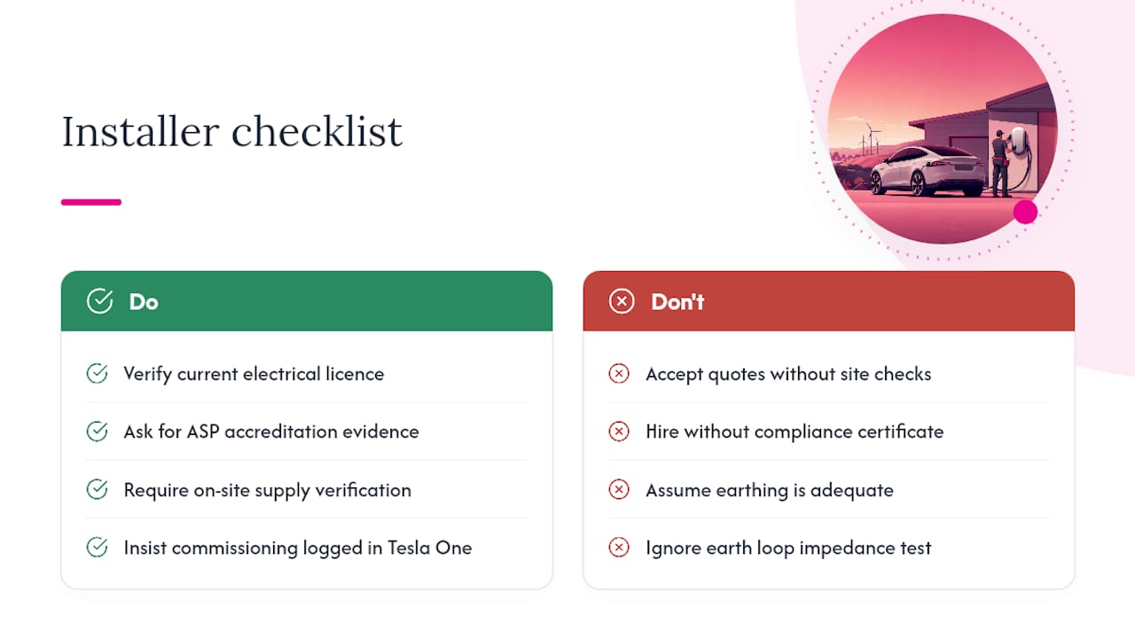
A compliant Wall Connector installation is Level 2 electrical work in most practical respects, even where it technically sits within a licensed electrician’s standard scope, because it touches supply capacity, switchboard protection, and earthing at the main distribution point. An installer working on your property should be able to produce a current electrical licence, evidence of ASP (accredited service provider) status where the job touches network‑connected infrastructure, and a clear record of similar EV charger installations completed to AS/NZS 3000 and the manufacturer’s own manual.
On‑site, a properly qualified installer runs through supply verification before quoting a final price, not after. That means checking actual switchboard capacity against the proposed circuit, confirming the property’s earthing system type, and testing earth loop impedance at the point of connection rather than assuming it’s adequate. Skipping this step is how installers end up quoting a 60 A circuit on a switchboard that genuinely can’t support it without an upgrade.
Once the physical install is done, the paperwork matters as much as the wiring. A proper job finishes with commissioning records showing every step completed in the Tesla One app, a compliance certificate for the electrical work itself, and test results confirming earth continuity, RCD function and breaker operation.
High Demand Electrical offers free site inspections specifically for Level 2 work, which matters here because supply capacity and switchboard condition genuinely can’t be assessed accurately over the phone. The EV charger load calculator is a useful first step for owners wanting a rough sense of whether their existing supply can handle a Wall Connector before booking an inspection, particularly for multi‑vehicle households weighing up power sharing against a supply upgrade.
Before hiring anyone, a homeowner should ask a short set of direct questions: what breaker size are you specifying and why, will you complete commissioning in the Tesla One app before you leave, what does the earth assurance test show on my property, and what documentation will I receive once the job’s done. A qualified installer answers all four without hesitation.
What surprises come up on real Tesla Wall Connector jobs?
The problems that actually cost time and money on Wall Connector installs rarely show up in a manual. Meter capacity is the most common one. A property’s main switchboard might have plenty of physical room for a new breaker, but the actual supply coming in from the street, and the meter rating attached to it, is what genuinely limits what the circuit can safely carry. That’s a conversation with the distribution network operator, not something a quick look at the switchboard resolves.
PME (protective multiple earthing) arrangements catch installers out on older properties and those with private power poles, where the earthing configuration doesn’t match the straightforward TN setup most installers expect. It’s exactly the kind of detail an EV charger installation job needs checked properly before wiring starts, not discovered halfway through.
Long feeder runs are the other recurring cost blowout, particularly on properties where the Wall Connector needs to sit near a detached garage or a car space well away from the switchboard. Voltage drop calculations that looked fine on paper for a 20‑metre run start failing once the actual measured distance turns out to be 35 metres with a few unavoidable bends around existing plumbing.
Homeowners sometimes make their own job harder by choosing a mounting spot for aesthetics rather than proximity to the switchboard, or by requesting outdoor placement in a spot with no practical route for a sealed conduit run. The fix is usually a five‑minute conversation before quoting, walking the property together and agreeing on a location that balances convenience against a sane cable run.
— Christopher
Book a free site inspection with High Demand Electrical
A DIY Wall Connector install might look tempting when the manual reads like a straightforward wiring diagram, but the earth assurance testing, continuous‑load breaker sizing and mandatory Tesla One commissioning steps covered here are exactly where unqualified attempts go wrong, and where NSW compliance rules require licensed sign‑off regardless. Free site inspections are important for Level 2 electrical work because supply capacity and earthing configuration cannot be accurately assessed without a proper inspection of the switchboard.

Every installation is carried out by licensed Level 2 electricians who handle the full job end to end: supply verification, breaker and conductor sizing, earth assurance testing, and full commissioning through the Tesla One app before handing over paperwork. If you’re unsure whether your current supply can handle a Wall Connector at all, the EV charger load calculator gives a useful first read before booking anything. The company emphasizes 24/7 availability for urgent issues and strict compliance with NSW electrical standards on every installation. Book a free site inspection through the Tesla EV charger installation page to get a firm quote before committing to anything.
Key manuals and support pages to keep on hand
Every installer working on a Gen 3 Wall Connector should have these open before touching a switchboard:
- The Gen 3 Wall Connector Installation Manual for Australia and New Zealand, which sets out region‑specific terminal ranges, mounting dimensions and wiring diagrams matched to Australian supply conventions.
- The global Gen 3 installation manual, covering earth assurance behaviour across different grid types and full mounting height specifications.
- Tesla’s own support page for installing a Wall Connector, which walks through the commissioning sequence in the Tesla One app step by step.
Each document covers a different layer of the job, and cross‑checking terminal ranges against the AU/NZ manual specifically avoids applying a spec from a different region’s wiring conventions by mistake.
Sources
- Gen3 Wall Connector Installation Manual AU NZ
- Installing a Wall Connector | Tesla Support
- Gen 3 J1772 Wall Connector manual (installation spec excerpt)
FAQ
What are the electrical requirements for a Tesla Wall Connector?
A compliant install needs a 230 V single‑phase or supported three‑phase supply, correctly sized copper conductors within the terminal’s accepted range, a permanent bonded earth path, and a breaker sized against continuous‑load rules, typically 60 A double‑pole for maximum single‑phase output on the Gen 3 J1772 Wall Connector. Commissioning through the Tesla One app is required afterwards to activate full functionality.
Can a Tesla Wall Connector do 22kW?
Yes, but only on a three‑phase supply drawing roughly 32 A per phase, since single‑phase output tops out around 13.8 kW even at the maximum 60 A breaker rating. Most Australian homes run single‑phase power, so reaching 22 kW usually means a three‑phase supply upgrade first.
Can you plug a Tesla into a regular 240 V outlet?
A Tesla can charge from a standard 10 A household outlet using the mobile connector, but charging speed is very slow, often adding only a small range overnight. A dedicated Wall Connector on its own circuit, installed by a licensed Level 2 electrician, delivers dramatically faster and more reliable charging.
Can I use a 60 amp breaker for a Tesla Wall Connector?
Yes, a 60 A double‑pole breaker is what Tesla specifies for maximum single‑phase output, provided the conductor size, switchboard capacity and continuous‑load derating all support it under AS/NZS 3000. An installer should verify actual supply capacity before committing to that breaker size rather than assuming it’s automatically available.
Can I install a Tesla Wall Connector myself?
The wiring, breaker sizing and earthing work involved fall under licensed electrical work in Australia, and NSW compliance rules require a qualified electrician to carry it out and certify it. Commissioning through the Tesla One app also assumes the underlying electrical work has already been verified as safe and correctly configured, which isn’t something to shortcut on a DIY basis.
Recommended
Powering Your Needs with Expertise
If you’re looking for a reliable, experienced, and prompt electrician, look no further than High Demand Electrical. We cater to all your electrical needs, from routine maintenance to emergency repairs and complete system installations. Our skilled team is committed to providing professional service that ensures your electrical systems run smoothly. Whether it's a small task or a large project, give us a call today. Let us meet all your electrical demands with the quality and reliability you deserve.